Seal ring and seal device

a sealing ring and sealing technology, applied in the direction of gearing, other chemical processes, conductors, etc., can solve the problems of increasing friction torque and self-abrasion, prone to lowering of the sealing property and the inability of the sealing ring to retain the oil film of the slidingly contacting surface in sliding conditions, so as to achieve the effect of reducing the friction torque and improving the fuel consumption of the automobil

Inactive Publication Date: 2005-04-26
NISSAN MOTOR CO LTD +1
View PDF2 Cites 22 Cited by
  • Summary
  • Abstract
  • Description
  • Claims
  • Application Information

AI Technical Summary

Benefits of technology

[0010]The present invention is made focusing on the problems described above in the related art. It is an object of the present invention to provide a seal ring capable of contributing to the improvement of fuel consumption of an automobile by effectively reducing the friction torque on a sliding surface thereof without damaging the sealing property during an operation under high pressure, and to provide a hydraulics seal device.

Problems solved by technology

However, while the fluororesin has an excellent low friction torque property, the fluororesin also exhibits an oil repellent property because its surface energy is small, and therefore, the seal ring cannot retain an oil film of the slidingly contacting surface in sliding conditions, particularly under high surface pressure where the oil film is thinned.
Thus, there has been a problem in that the friction torque and the amount of self-abrasion are increased as the time elapses.
Since the fluororesin has a poor creep-resistant property, particularly at high temperature, the sealing property thereof is prone to be lowered.
However, if such a filler material is added to the fluororesin, when an inner circumferential surface of a seal ring groove or a housing serving as a partner during the sliding movement is non-iron metal such as an aluminum alloy, the abrasion on the partner side during the sliding movement has sometimes been increased, thus deteriorating the sealing property.
On the other hand, if the fiber filler material and the metal filler material are not added to the fluororesin in order to prevent the above-described abrasion, the improvement of the load-resistant property is insufficient, and the self-abrasion of the seal ring under the high surface pressure is increased, thus also deteriorating the sealing property, which has been regarded as a problem.

Method used


Image

  • Seal ring and seal device
  • Seal ring and seal device
  • Seal ring and seal device

Examples


example 1

[0048]For the fluororesin serving as the base material of the seal ring 10, tetrafluoroethylene with an excellent low friction torque property among fluororesins was used. The molding powder of this resin (G-163 made by Asahi Glass Company) was irradiated with an electron beam (acceleration voltage of 2 MeV) by exposure to 100 kGy under an atmosphere with an oxygen partial pressure of 0.133 kPa (1 Torr), a nitrogen partial pressure of 106.4 kPa (800 Torr) and a heating condition of 350° C. Thus, modified fluororesin was produced. Then, this modified resin was milled by a jet mill until a mean particle diameter thereof reached approximately 20 μm.

[0049]Next, the above-described modified fluororesin of 25 vol % was compounded with unmodified tetrafluoroethylene molding powder (G-163 made by Asahi Glass Company) of 65 vol %. Moreover, as the metal powder having a Vickers hardness equivalent to or more than that of the partner material, stainless steel flake powder (St-S400 mesh made by...

example 2

[0052]Similarly to Example 1, the modified fluororesin of 20 vol % was compounded with the unmodified tetrafluoroethylene molding powder (G-163 made by Asahi Glass Company) of 50 vol %. Moreover, as the metal powder having a Vickers hardness equivalent to or more than that of the partner material, the stainless steel flake powder (St-S400 mesh made by Fukuda Metal Foil & Powder Co., Ltd.) of 10 vol % was added in the compounded powder. Furthermore, as the synthetic resin having the surface energy ranging from +0 N / cm to 20×10−5 N / cm inclusive with respect to the surface energy of the operating oil to be hermetically sealed, polyamideimide powder (TORLON 4203L made by Amoco) of 20 vol % was added in the compounded powder.

[0053]Note that the polyamideimide was selected as the above-described synthetic resin because, as shown in the following Table 1, it had a surface energy larger than the operating oil for automatic transmission (Matic J made by Idemitsu Kosan Co., Ltd.) 28 used in a...

example 3

[0056]Similarly to Example 1, as the metal powder having a Vickers hardness equivalent to or more than that of the partner material, the stainless steel flake powder (St-S400 mesh made by Fukuda Metal Foil & Powder Co., Ltd.) of 10 vol % was compounded with the unmodified tetrafluoroethylene molding powder (G-163 made by Asahi Glass Company) of 70 vol %. Moreover, as the synthetic resin having a surface energy ranging from +0 N / cm to 20×10−5 N / cm inclusive with respect to the surface energy of the operating oil to be hermetically sealed, polyamideimide powder (TORLON 4203L made by Amoco) of 20 vol % was added in the compounded powder.

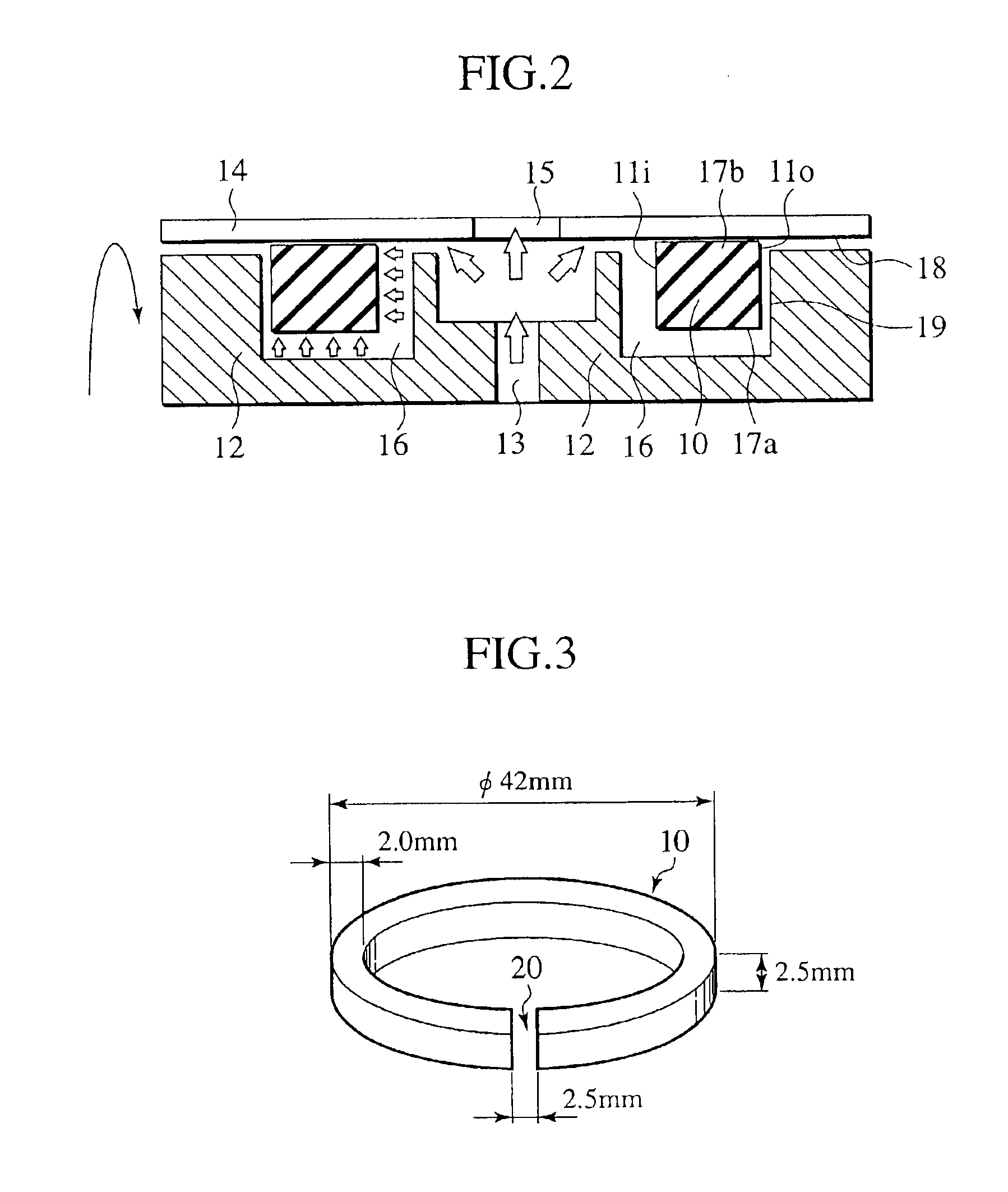
[0057]The above-described compound powder was machined into the seal ring 10 illustrated in FIG. 3 under similar conditions to those of Example 1. Thus, the seal ring of this example was obtained.


PUM

PropertyMeasurementUnit
pressureaaaaaaaaaa
surface energyaaaaaaaaaa
partial pressureaaaaaaaaaa

Abstract

A seal ring seals operating oil hermetically and is attached to an annular seal ring groove provided on an outer circumference of a shaft member. The seal ring comprises fluororesin, metal powder having a hardness equal to or more than that of any of a side surface of the seal ring groove serving as a sliding partner and an inner circumferential surface of a housing engaged relatively rotatable with the outer circumference of the shaft member, and modified fluororesin formed by irradiating an ionizing radiation in a range from 1 kGy to 10 MGy inclusive in a state of being heated up to a melting point thereof or higher under an inert gas atmosphere with an oxygen partial pressure of 1.33 kPa or less.

Description

BACKGROUND OF THE INVENTION[0001]1. Field of the Invention[0002]The present invention relates to a seal ring used for hermetically sealing operating oil of relative rotation portions in an automatic transmission mainly used in an automobile or the like and to a hydraulics seal device using the seal ring.[0003]2. Description of the Related Art[0004]Heretofore, an automatic transmission used in a vehicle such as an automobile has included a torque converter, gears, a brake and a multi-plate clutch. The automatic transmission (hereinafter, also referred to as “AT”) requires a clutch engagement for transmission and adopts a construction in which this clutch engagement is performed by oil pressure. Therefore, sealing is required for relatively rotating portions in a hydraulics circuit, a seal ring is provided in a ring groove in one of the members constructing the portions, and the seal ring is designed to slidingly contact the sidewall surface of the ring groove while being thrust on an...

Claims


Application Information

Patent Timeline
Patent Type & Authority Patents(United States)
IPC IPC(8): C09K3/10F16J15/12F16J15/18C08J3/28C08K3/08C08L27/12F16H3/66
CPCC09K3/1009F16J15/441F16J15/126F16H3/663
Inventor OTA, TOMOHITOHASHIMOTO, TOMIHITOYAMAMOTO, YASUAKIKUSANO, HIROO
Owner NISSAN MOTOR CO LTD
Why Eureka
Try Eureka