Symmetric beamline and methods for generating a mass-analyzed ribbon ion beam

a beamline and ribbon technology, applied in the field of ion implantation systems, can solve the problems of increasing the cost of individual wafers, beam blowing, and providing a high current beam, and achieves the effect of facilitating simplification of implantation systems, not adversely affecting implantation uniformity, and high conducive to maintaining beam integrity

Inactive Publication Date: 2005-04-26
AXCELIS TECHNOLOGIES
View PDF19 Cites 19 Cited by
  • Summary
  • Abstract
  • Description
  • Claims
  • Application Information

AI Technical Summary

Benefits of technology

[0008]The symmetry of the beamline system provides one to one imaging of the source ions of a desired mass onto the target wafer, thereby facilitating control of process parameters such as dose uniformity and implant angular integrity. The invention may be advantageously employed in providing ribbon beams having transverse widths of about 300 mm or more (e.g., 400 mm wide in one implementation) having uniform density profiles, whereby single-scan implantation of large (e.g., 300 mm) wafers can be achieved without complex and costly raster scanning apparatus. Thus, the invention facilitates simplification of implantation systems. In addition, the invention provides a relatively large ion beam cross-section throughout most of the beamline system, whereby the space charge is diffused, which is highly conducive to maintaining beam integrity in low energy implantation applications. Another advantage of the beamline system symmetry is that the total path length or travel distance of ions from the source to the target is nearly constant for all portions of the ribbon beam. Consequently, transport losses are approximately uniform across the beam, and hence do not adversely impact implantation uniformity. Moreover, the architectures of the invention helps in preventing contaminants and particles from the source and beam dumps from reaching the target wafer.
[0009]Ion implantation systems and beamline systems therefor are provided, in which a ribbon beam of a relatively large aspect ratio is mass analyzed and collimated to provide a mass analyzed ribbon beam for use in implanting one or more workpieces. The system provides a symmetrical beam path by which the ribbon-beam profile, including aspect ratio, of the initial and analyzed beams are virtually the same. In this regard, the ions traveling through the beamline encounter equidistant trajectories, whereby the travel distance for each ion is the same as that of other ions in the beam. In one example, the beamline system comprises two similar magnets, where the first magnet mass analyzes the ribbon beam to provide an intermediate mass analyzed ion beam, and the second magnet collimates the intermediate beam to provide a uniform mass analyzed ribbon beam to an end station. The symmetrical system provides equidistant beam trajectories for ions across the elongated beam width so as to mitigate non-linearities in the beam transport through the system, such that the resultant mass analyzed beam is highly uniform.

Problems solved by technology

Coupled with higher device densities, the larger wafer size increases the cost of individual wafers.
Such systems, however, suffer from difficulties in providing a high current beam at low energies due to the high beam density associated therewith, wherein the high beam density tends to result in beam blow-up due to space charge.

Method used


Image

  • Symmetric beamline and methods for generating a mass-analyzed ribbon ion beam
  • Symmetric beamline and methods for generating a mass-analyzed ribbon ion beam
  • Symmetric beamline and methods for generating a mass-analyzed ribbon ion beam

Examples


Embodiment Construction

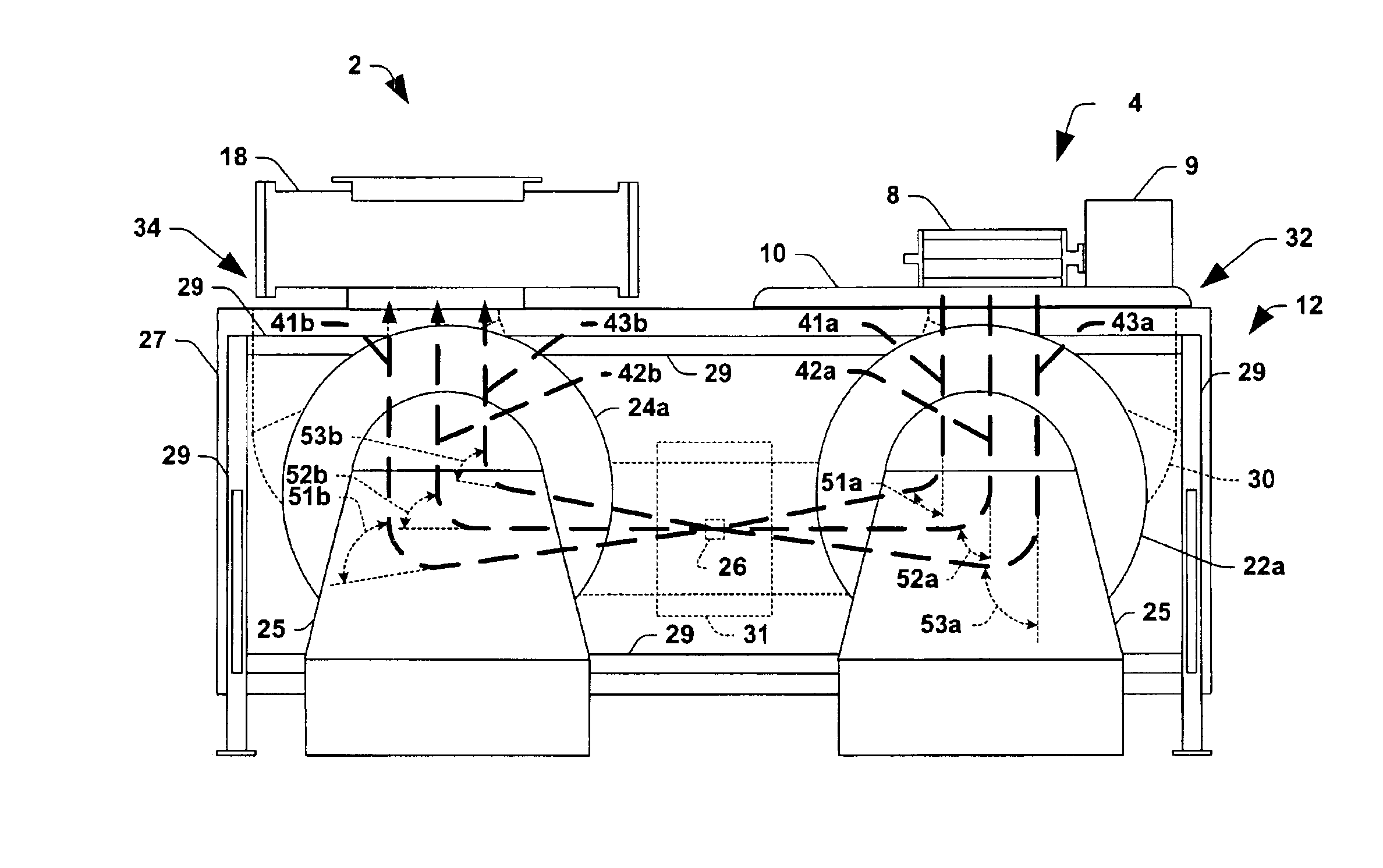
[0029]The present invention will now be described with reference to the drawings wherein like reference numerals are used to refer to like elements throughout. The invention provides methods and systems for provision of a mass analyzed ribbon-beam for ion implantation of workpieces such as semiconductor wafers. One implementation of the invention is illustrated and described hereinafter with respect to the drawing figures. The illustrations and following descriptions are exemplary in nature, and not limiting. Thus, it will be appreciated that variants of the illustrated systems and methods and other such implementations apart from those illustrated herein are deemed as falling within the scope of the present invention and the appended claims.

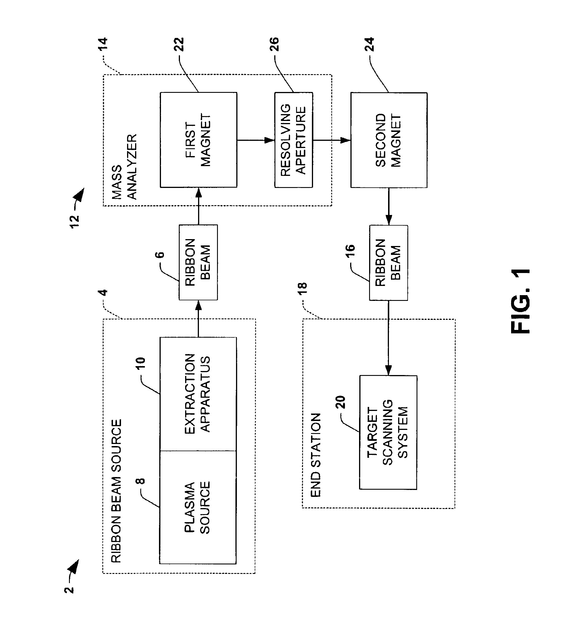
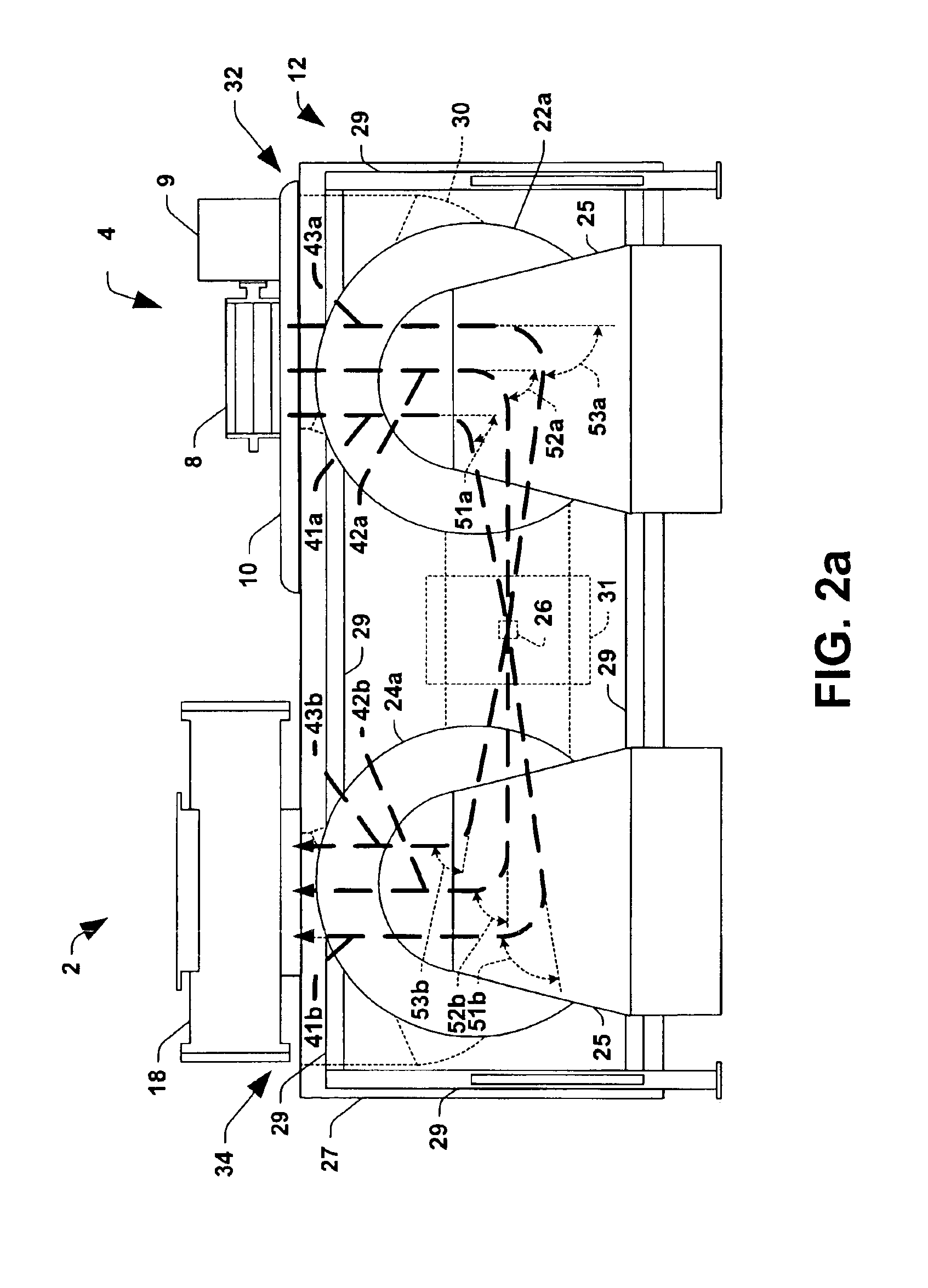
[0030]Referring initially to FIGS. 1, and 2a-2c, the invention provides an ion implantation system 2 comprising an ion source 4 for producing an elongated (e.g., ribbon-shaped) ion beam 6 along a longitudinal beam path. The ion beam source 4 inc...


PUM


Abstract

Ion implantation systems and beamlines therefor are disclosed, in which a ribbon beam of a relatively large aspect ratio is mass analyzed and collimated to provide a mass analyzed ribbon beam for use in implanting one or more workpieces. The beamline system comprises two similar magnets, where the first magnet mass analyzes the ribbon beam to provide an intermediate mass analyzed ion beam, and the second magnet collimates the intermediate beam to provide a uniform mass analyzed ribbon beam to an end station. The symmetrical system provides equidistant beam trajectories for ions across the elongated beam width so as to mitigate non-linearities in the beam transport through the system, such that the resultant mass analyzed beam is highly uniform.

Description

RELATED APPLICATION[0001]This application is a Continuation-In-Part of Ser. No. 10 / 136,047 filed May 1, 2002, now U.S. Pat. No. 6,664,547, which is entitled “Ion Source Providing Ribbon Beam with Controllable Density Profile”.FIELD OF THE INVENTION[0002]The present invention relates generally to ion implantation systems, and more particularly to symmetric beamline systems and methods for generating mass-analyzed ribbon ion beams in an ion implantation system.BACKGROUND OF THE INVENTION[0003]Ion implantation systems are used to dope semiconductors with impurities in integrated circuit manufacturing. In such systems, an ion source ionizes a desired dopant element, which is extracted from the source in the form of an ion beam of desired energy. The ion beam is then directed at the surface of a semiconductor wafer in order to implant the wafer with the dopant element. The ions of the beam penetrate the surface of the wafer to form a region of desired conductivity, such as in the fabrica...

Claims


Application Information

Patent Timeline
IPC IPC(8): H01J37/08H01J27/00H01J37/04H01J27/16H01J27/06H01J37/317H01J27/02H01J37/05H01L21/265
CPCH01J37/05H01J37/08H01J37/3171H01J2237/31701H01J2237/0835
Inventor BENVENISTE, VICTOR M.
Owner AXCELIS TECHNOLOGIES
Why Eureka
Try Eureka