LED cross-linkable phosphor coating

a cross-linkable phosphor coating and cross-linkable technology, which is applied in the manufacture of electrode systems, electric discharge tubes/lamps, and discharge tubes luminescnet screens, etc., can solve the problems of reducing the light output, so as to increase the intensity of the converted light output

Inactive Publication Date: 2005-05-10
GENERAL ELECTRIC CO
View PDF16 Cites 85 Cited by
  • Summary
  • Abstract
  • Description
  • Claims
  • Application Information

AI Technical Summary

Benefits of technology

[0015]One advantage of the present invention is that light is produced with a relatively uniform color over a wide range of viewing angles.
[0016]Another advantage of the present invention is that the intensity of the converted light output is increased, due to the optimization of the phosphor layer thickness.
[0017]Other advantages of the present invention derive from the use of a UV-curable material

Problems solved by technology

When the die is coated with a layer of phosphor, the non-uniformity in the radiation emitted by the LED results in non-uniform excitation of the phosphor and may cause non non-uniformity in the color and/or intensity of the light emitted by the device.
With phosphor coated visible LED's, too thick of a phosphor coating over the less light intense areas reduces the light output and shifts the color of the output in those regions by not allowing enough of the LED wavelength emission to pass through to balance the color from the phosphor emission.
Alternatively, too thin of a coating over the more intense areas of the LED allows too much of the LED wavelength emission to pass through, resulting in light that is not white, since it is dominated by the LED color.
In the case of a UV-emitting LED, harmf

Method used


Image

  • LED cross-linkable phosphor coating
  • LED cross-linkable phosphor coating
  • LED cross-linkable phosphor coating

Examples


Embodiment Construction

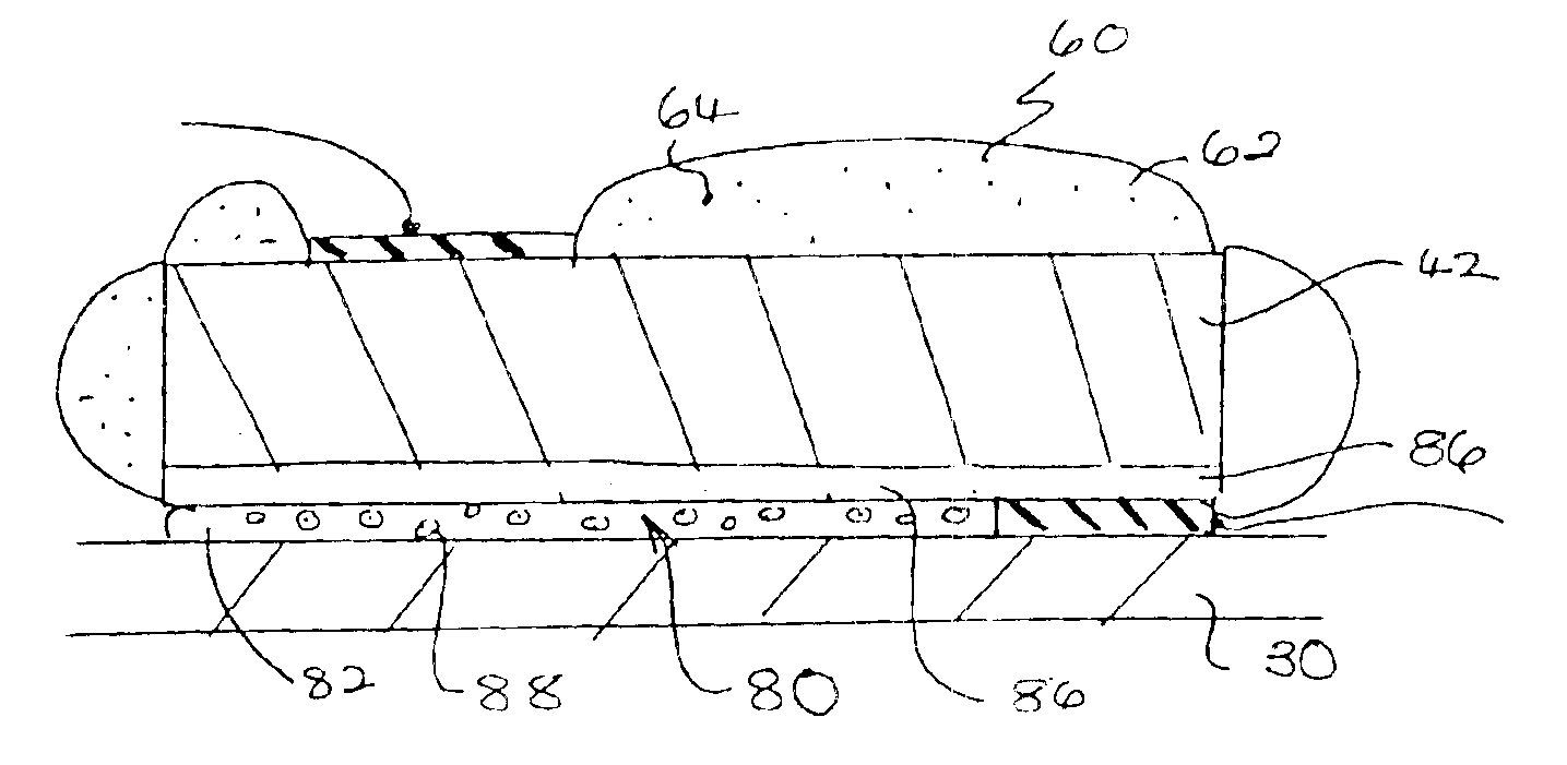
[0029]A phosphor coating with self adjusting variable thickness is made by combining at least one phosphor with a material which is curable by light of a selected wavelength. The phosphor-impregnated curable material is applied to a die (laser diode or light emitting diode). Light from the die is then used to cure the material to a thickness that varies across the die in relation to the intensity of the light emitted.

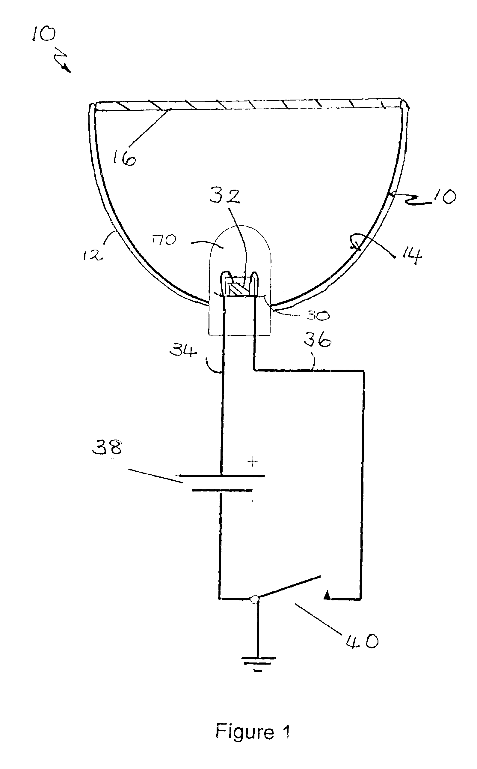
[0030]With reference to FIG. 1, a light source, such as a lamp 10, includes a cup-shaped reflector housing 12, which is coated on its interior surface with a reflective coating 14 capable of reflecting light in the UV and visible range of the electromagnetic spectrum. As used herein, the term “light” encompasses radiation in the UV and IR regions of the electromagnetic spectrum in addition to light in the visible region of the spectrum—i.e., all radiation emitted by or generated within the light source.

[0031]The reflector housing 12 may have a variety of configurations ...


PUM


Abstract

A light source (10) includes a light emitting component (32), such as a UV/blue light emitting diode or laser diode coated with a layer (60) of a phosphor material (64). The phosphor material converts a portion of the light emitted by the light emitting component to light of a longer wavelength, such as yellow light. The thickness d of the layer varies across the light emitting component in relation to the intensity of light emitted by the light emitting component. This maintains a uniform color of the emission from the light source while minimizing the loss in light intensity (brightness) due to the presence of the phosphor.

Description

[0001]This application claims the benefit of application Ser. No. 09 / 633,527, filed Aug. 7, 2000, now U.S. Pat. No. 6,747,406, the disclosure of which is incorporated herein in its entirety, by reference.BACKGROUND OF THE INVENTION[0002]This invention relates to a light emitting device comprising a light emitting diode or laser diode (LED) and an excitable phosphor, which surrounds the LED chip. The phosphor is contained within a light transmissive medium of variable thickness for a more uniform emission of the light output. The invention finds particular application in combination with a UV / Blue LED and a phosphor or blend of phosphors, for converting LED-generated ultraviolet (UV) and / or blue light into white light for general illumination purposes. It should be appreciated, however, that the invention is also suitable to the conversion of light from other light sources to light of a different wavelength.[0003]The advent of GaN-based epitaxial structures has lead to the developmen...

Claims


Application Information

Patent Timeline
IPC IPC(8): H01L33/00H01S5/00H01S5/028H01L33/50
CPCH01L33/508H01L2224/8592H01L2224/48463H01S5/028
Inventor BORTSCHELLER, JACOB C.WOJNAROWSKI, ROBERT J.
Owner GENERAL ELECTRIC CO
Why Eureka
Try Eureka