Multi-layered radiation converter

Inactive Publication Date: 2005-05-10
C-RAD IMAGING AB
View PDF8 Cites 18 Cited by
  • Summary
  • Abstract
  • Description
  • Claims
  • Application Information

AI Technical Summary

Benefits of technology

[0025]As indicated above, the multi-layered converter architecture according to the invention opens up for the possibility to convert radiation on very different energy levels in the same converter structure. The basic idea can be taken one step further by combining several individual converter stacks (oriented towards different energy intervals) in the same detector with a common sensor device. By arranging a first stack of mutually staggered converter layers adapted for photons of lower energy such as X-rays, and a second stack of mutually staggered converter layers adapted for photons of higher energy such as gamma radiat

Problems solved by technology

However, as the photon energy increases, gas conversion becomes less attractive since the photoelectric capture cross section falls rapidly and the photoelectron range increases.
This results in degraded efficiency, as well as heavily deteriorated spatial resolution due to the extended tracks of the long-range electrons.
However, both of these developments have not received any wide spread use due to the fact that the efficiency of the converters is still relatively low (a few %).
The low efficiency is associated with the fact that electrons created by gamma radiation inside the converters have a very short mean free pa

Method used


Image

  • Multi-layered radiation converter
  • Multi-layered radiation converter
  • Multi-layered radiation converter

Examples


Embodiment Construction

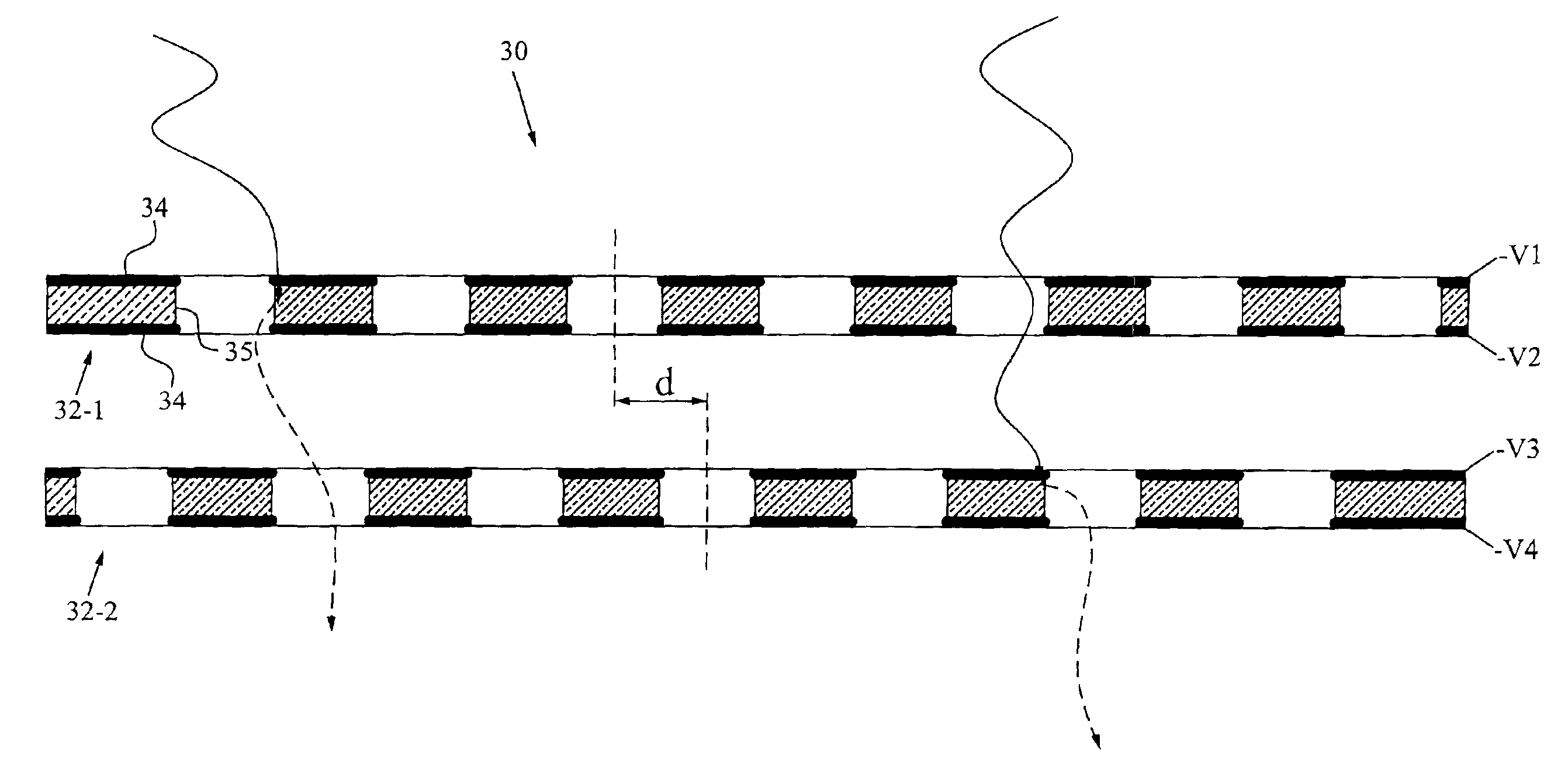
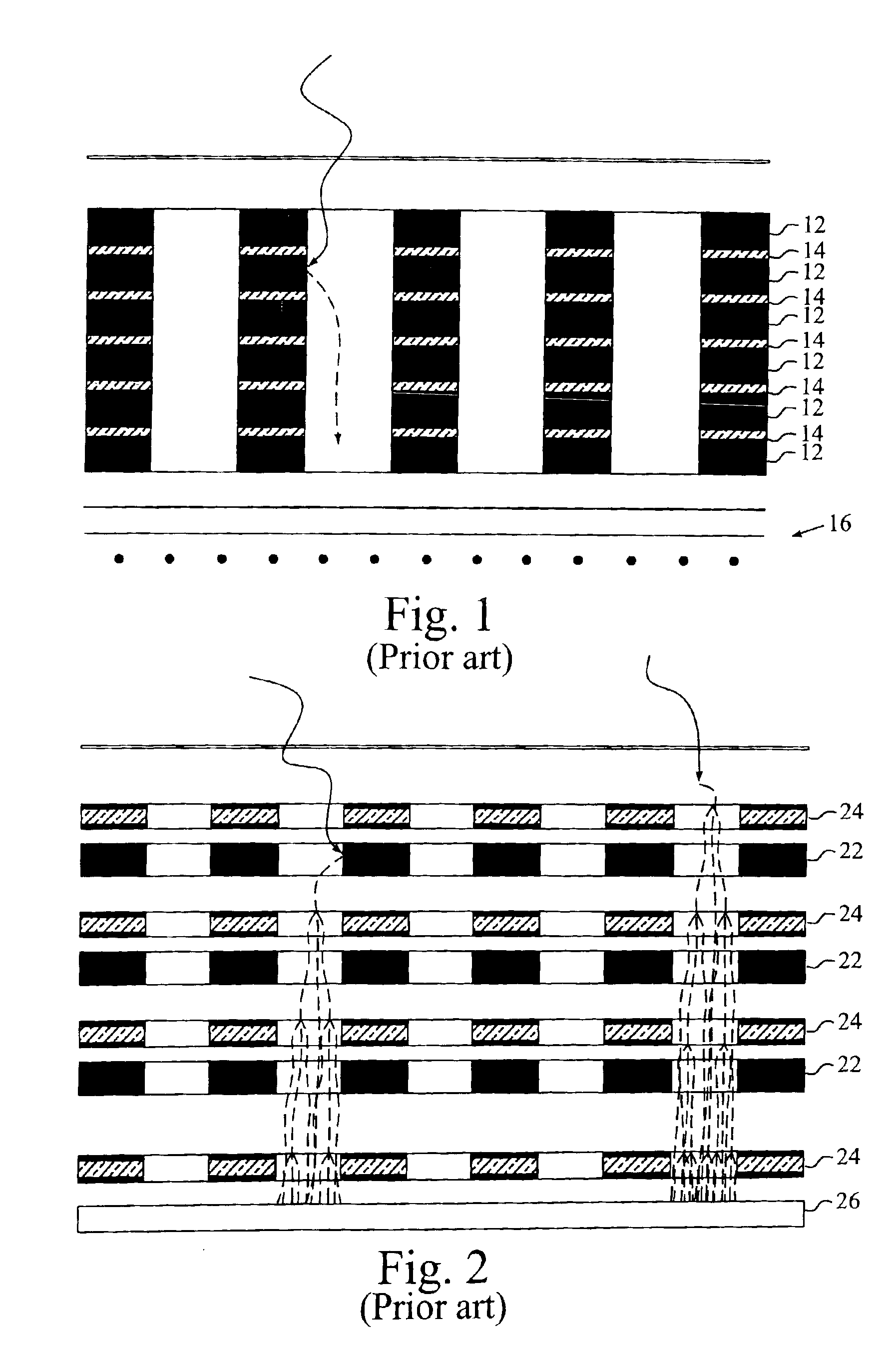
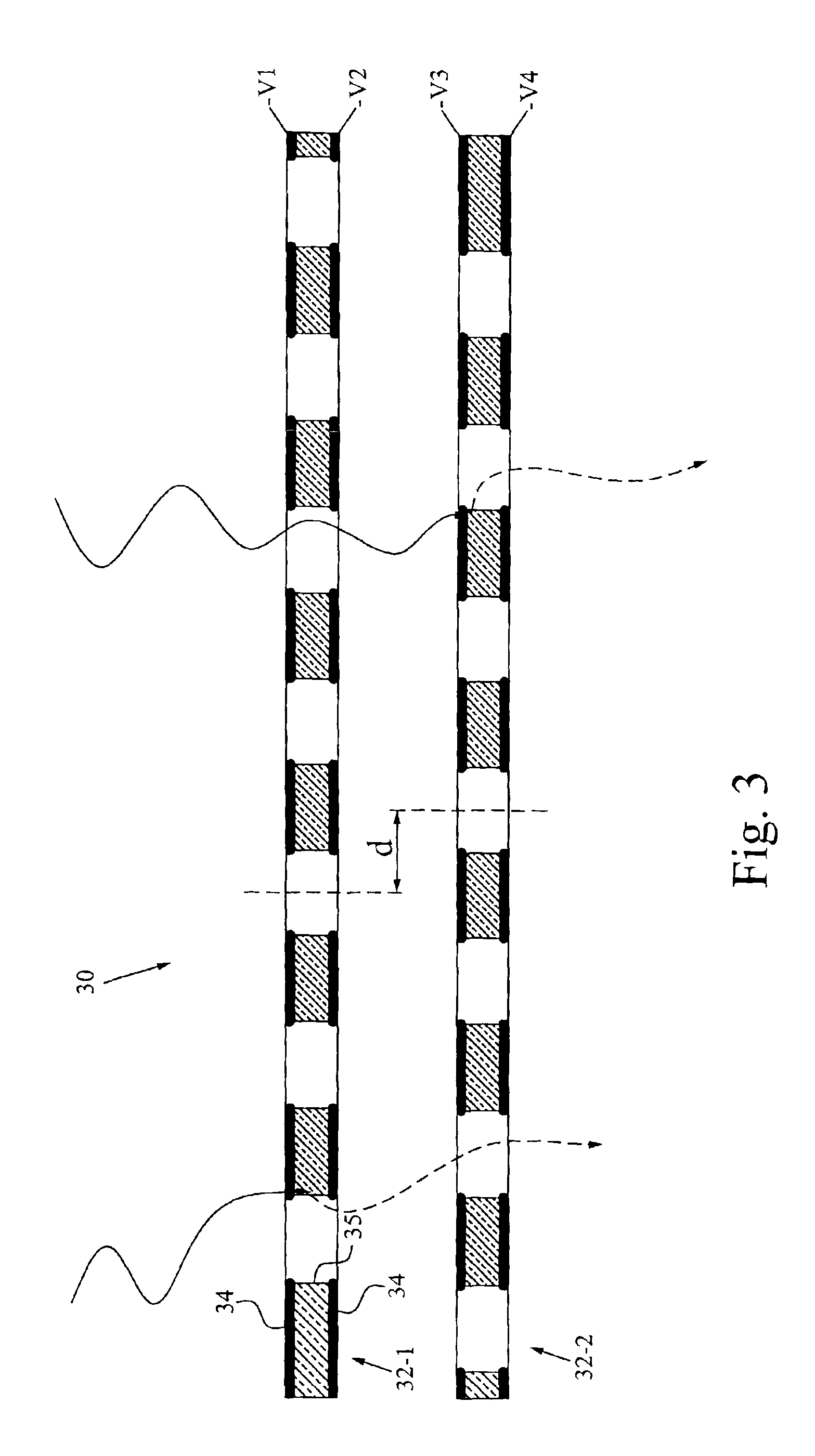
[0042]Throughout the drawings, the same reference characters will be used for corresponding or similar elements.

[0043]FIG. 3 is a schematic cross-sectional view of a converter stack according to a preferred embodiment of the invention. In this particular example, the converter stack 30 comprises two converter layers 32-1 and 32-2, each of which has a number of drift holes defined therein. Each converter layer preferably includes two electrode layers 34 separated by a support structure 35. The support structure 35 is normally made of an insulating material, and the electrode layers 34 may simply be a metallization on both sides of the insulating material. The converter layers 32-1 and 32-2 are preferably arranged in a conventional framework (not shown), possibly using dielectric spacers if required.

[0044]The converter stack 30 generally has connection terminals for connecting the converter to an electric field generator for providing an electric drift field in a direction substantial...


PUM


Abstract

The invention relates to a multi-layered radiation converter, a radiation detector comprising such a converter as well as a radiation-based imaging system using such a detector. Each converter layer (32) in the radiation converter is adapted for interaction with incident radiation to cause the emission of electrons into drift holes defined in the converter layer. The drift holes of one converter layer (32-1) are staggered with respect to the drift holes of another converter layer (32-2). By mutually shifting the converter layers such that the drift holes of two different layers are no longer well-aligned, but rather staggered with respect to each other, the effective conversion area will be increased, and the probability of incoming radiation passing through the stack without interaction with the converter layers will be significantly reduced. In this way, high absorption efficiency for incident radiation inside the multi-layered converter structure is ensured, while still maintaining transparency for emitted electrons through the drift holes.

Description

TECHNICAL FIELD OF THE INVENTION[0001]The present invention generally concerns radiation converters and radiation detectors, and more particularly the use of such converters and detectors in radiation-based imaging systems for applications such as medical imaging and non-destructive testing.BACKGROUND OF THE INVENTION[0002]Radiation detectors are used for detection of incoming radiation such as X-rays, gamma photons and charged / uncharged particles, in a wide range of different applications. For detection of photons of various energies, the incoming photons are converted to electrons through electromagnetic interactions, including the photoelectric effect, pair production and the Compton effect. The emitted electrons are normally multiplied by a multiplication structure to produce a multiplicity of secondary electrons and / or photons, which in turn may be detected by a suitable sensor device.[0003]For low-energy photons, gas conversion is very successful with almost 100% efficiency co...

Claims


Application Information

Patent Timeline
IPC IPC(8): G01N23/02G01N23/083G01T1/185G01T1/161G01T1/00G01T1/29
CPCG01T1/2935
Inventor BRAHME, ANDERSIACOBAEUS, CHRISTIANOSTLING, JANINAPESKOV, VLADIMIR
Owner C-RAD IMAGING AB
Why Eureka
Try Eureka