Solid electrolytic capacitor and manufacturing method thereof

a technology of solid electrolytic capacitors and manufacturing methods, which is applied in the direction of electrolytic capacitors, capacitor electrodes, liquid electrolytic capacitors, etc., can solve the problems of difficult to reduce the achieve the reduction of equivalent serial resistance in a high frequency region, the effect of increasing the conductivity of the metal layer, and increasing the contact resistance between the carbon layer and the metal layer

Active Publication Date: 2005-05-17
SANYO ELECTRIC CO LTD
View PDF5 Cites 23 Cited by
  • Summary
  • Abstract
  • Description
  • Claims
  • Application Information

AI Technical Summary

Benefits of technology

[0013]In this case, the conductivity of the metal layer is increased because of the high conductivity of silver, gold, or platinum, thereby making the contact resistance between the carbon layer and the metal layer even smaller.
[0014]The metal layer may include a protective colloid. In this case, flocculation of the metal particles that may occur during preparation of the metal paste is prevented. Accordingly, the metal particles are uniformly dispersed in the metal paste, so that the contact resistance between the carbon layer and the metal layer is made even smaller. As a result, the equivalent serial resistance in a high frequency region is further reduced.

Problems solved by technology

In the case of a cathode formed by a carbon layer and a silver paste layer, in particular, the contact resistance between the carbon layer and the silver paste layer is attributed to a rise in the ESR, thereby making it difficult to reduce the ESR in a high frequency region.

Method used


Image

  • Solid electrolytic capacitor and manufacturing method thereof
  • Solid electrolytic capacitor and manufacturing method thereof
  • Solid electrolytic capacitor and manufacturing method thereof

Examples


examples

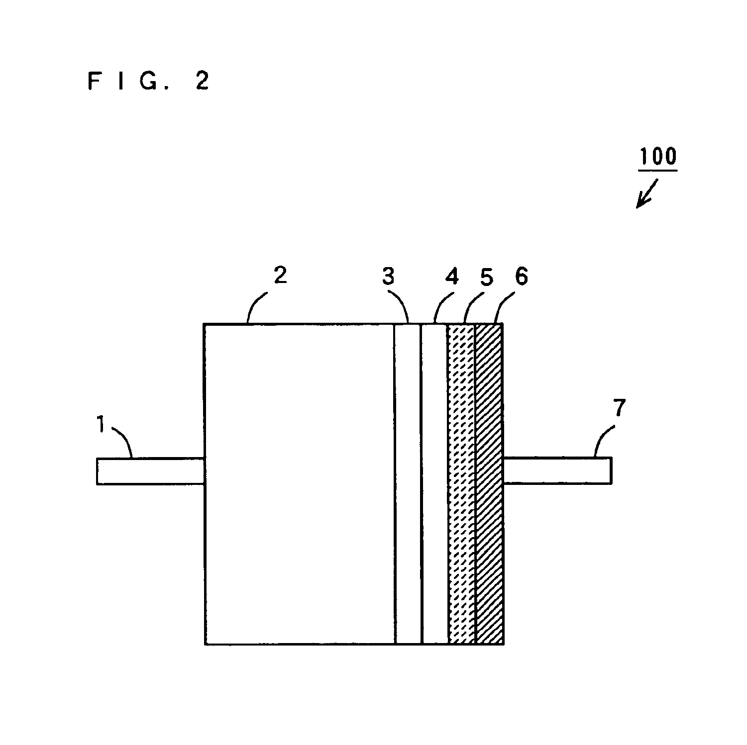
[0054]In the following Examples, solid electrolytic capacitors 100 were prepared by the manufacturing method according to the above-mentioned embodiment to evaluate the ESRs.

[0055]FIG. 2 is a schematic diagram of the solid electrolytic capacitor 100 prepared in inventive examples 1 to 12 and a comparative example.

##ventive examples 1-7

Inventive Examples 1-7

[0056]First, in the inventive examples 1 to 7, the solid electrolytic capacitors 100 were prepared in a following method under following conditions by setting the average particle diameters of the silver particles to 0.009 μm, 0.01 μm, 0.03 μm, 0.05 μm, 0.06 μm, 0.07 μm, and 0.09 μm, respectively.

[0057]Using polyethyleneimine as a protective colloid, 70% by weight of silver particles and 30% by weight of polyethyleneimine were mixed. Then, 60% by weight of the mixed substance and 40% by weight of an organic solvent of ethanol were mixed to prepare a silver paste.

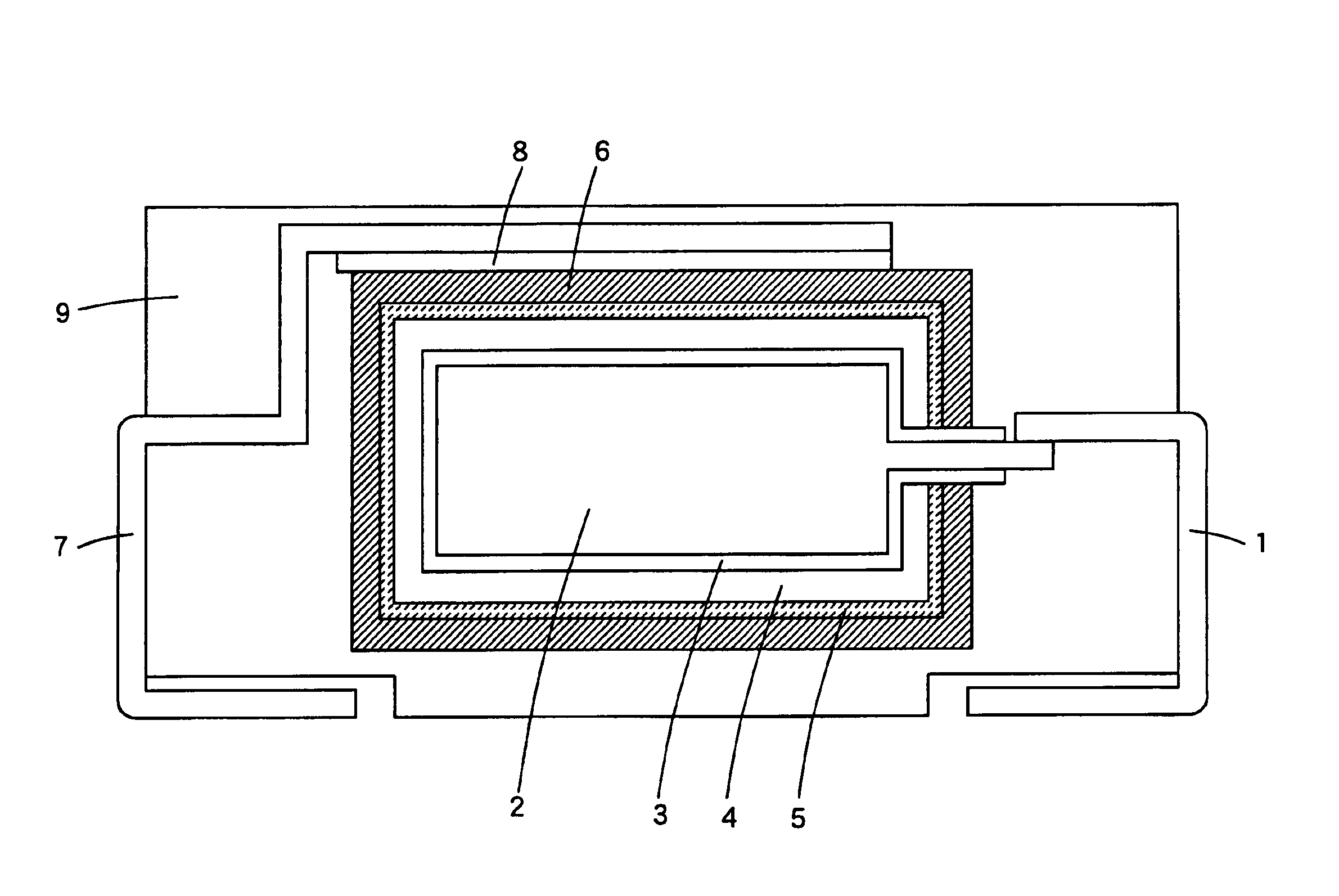
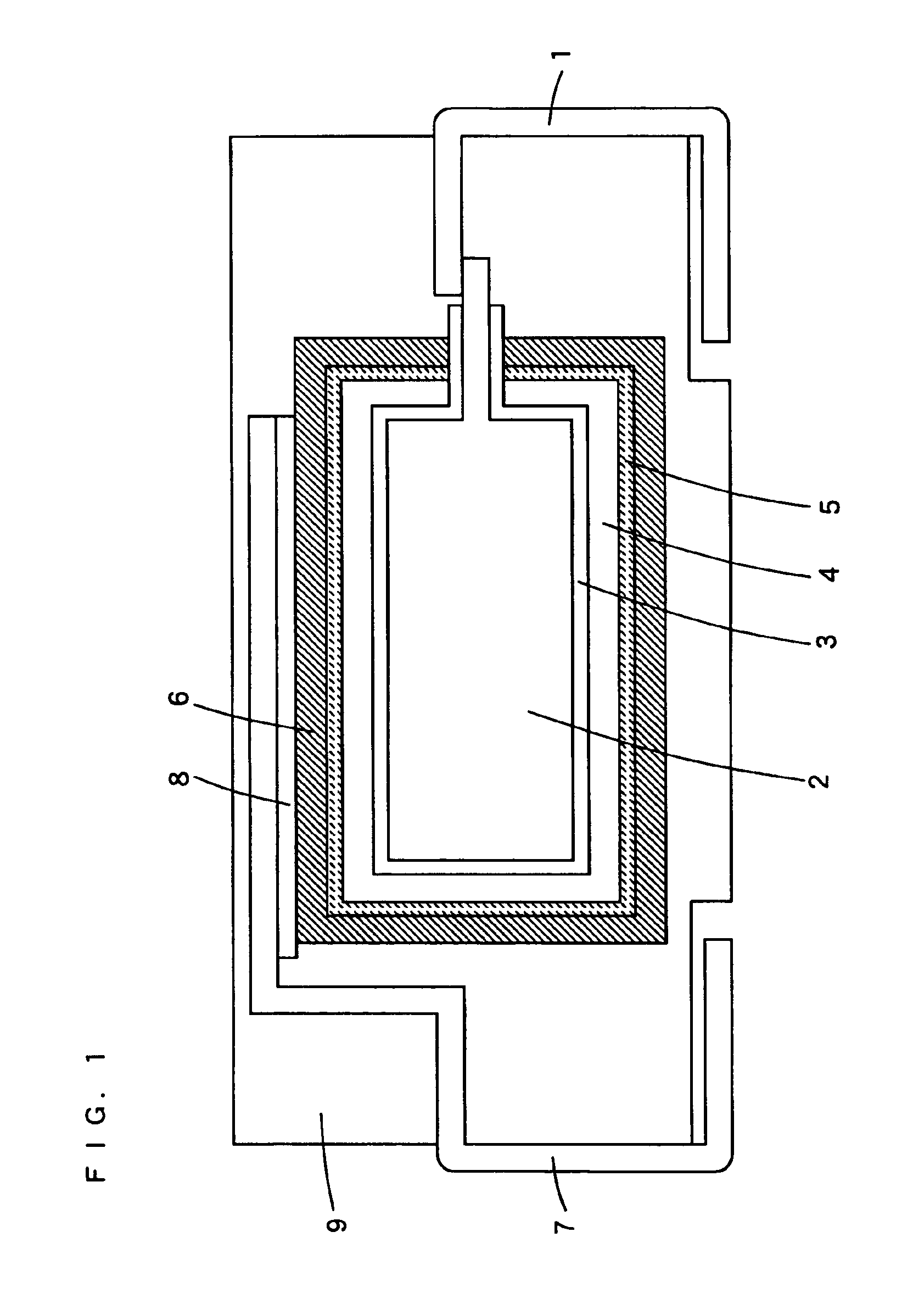
[0058]Subsequently, an anode 2 composed of a porous sinter was formed by sintering the powder of tantalum particles, and the formed anode 2 was anodized in an aqueous solution of phosphoric acid to form a dielectric layer 3 composed of a dielectric oxide film on the surface of the anode 2.

[0059]The surface of the dielectric layer 3 was then coated with an electrolyte 4 composed of polypyrrole by electro...

##ventive examples 8-12

Inventive Examples 8-12

[0068]In the inventive examples 8 to 12, the solid electrolytic capacitors 100 were prepared in the same manner under the same conditions as in the inventive examples 1 to 7 except that the average silver particle diameters were 0.03 micrometers for each, and the drying temperatures for the silver pastes were set to 140° C., 145° C., 150° C., 160° C., and 170° C., respectively. The inventive example 10 was the same as the aforementioned inventive example 3.

[0069](Evaluation)

[0070]The solid electrolytic capacitors 100 of the inventive examples 8 to 12 were each measured for the ESRs at a frequency of 100 kHz using an LCR meter.

[0071]Table 2 shows the ESR measurement results of the solid electrolytic capacitors 100 of the inventive examples 8 to 12. Note that the respective ESR measurement results of the solid electrolytic capacitors 100 of the inventive example 8 to 12 are normalized by the ESR measurement result of the solid electrolytic capacitor of the inven...


PUM

PropertyMeasurementUnit
particle diameteraaaaaaaaaa

Abstract

A solid electrolytic capacitor has a structure in which a dielectric layer, an electrolyte, a carbon layer, and a metal layer are formed in this order on the surface of an anode. The anode is composed of a porous sinter of tantalum particles. The dielectric layer is composed of a dielectric oxide film formed by anodizing the surface of the anode in an aqueous solution of phosphoric acid, for example. The electrolyte is composed of a conductive polymer, such as polypyrrole or polythiophene. The metal layer is formed by preparing a silver paste by mixing silver particles having an average particle diameter of not larger than 0.05 μm, a protective colloid, and an organic solvent, and applying the silver paste on the surface of the carbon layer, and drying the silver paste at approximately 150° C. or higher.

Description

BACKGROUND OF THE INVENTION[0001]1. Field of the Invention[0002]The present invention relates to a solid electrolytic capacitor and a manufacturing method thereof.[0003]2. Description of the Background Art[0004]In accordance with recent trend in increasing the frequency of electronic equipment such as personal computers, instantaneous supply of current to electronic circuits is required. For this reason, it is desired to develop solid electrolytic capacitors having a smaller value of equivalent serial resistance (hereinafter referred to as ESR).[0005]It is noted here that the ESR is the sum of dielectric loss, resistivity of an electrolyte, and contact resistance between the electrolyte and a cathode. In a high frequency region, the resistivity of an electrolyte and the contact resistance between the electrolyte and a cathode are predominant.[0006]In general, cathodes formed by two layers, a carbon layer and a silver paste layer, are used for solid electrolytic capacitors (Electroch...

Claims


Application Information

Patent Timeline
Patent Type & Authority Patents(United States)
IPC IPC(8): H01G9/022H01G9/028H01G9/00H01G9/04H01G9/004H01G9/14H01G9/145H01G9/15H01G9/042
CPCH01G9/042H01G9/0425H01G11/48H01G11/56H01G9/15Y02E60/13
Inventor TAKATANI, KAZUHIROYANO, MUTSUMIKIMOTO, MAMORU
Owner SANYO ELECTRIC CO LTD
Why Eureka
Try Eureka