Missile thrust system and valve with refractory piston cylinder

a technology of refractory pistons and thrust systems, applied in the field of pneumatic valves, can solve the problems of linkage and wear problems, valves need not necessarily be able to cope with these temperature environments, and cannot meet the requirements of certain drawbacks, so as to achieve better and more predictably directed and controlled effects

Inactive Publication Date: 2005-05-24
HONEYWELL INT INC
View PDF36 Cites 21 Cited by
  • Summary
  • Abstract
  • Description
  • Claims
  • Application Information

AI Technical Summary

Benefits of technology

[0013]In view of the foregoing disadvantages, the present invention provides new missile and valve construction that withstands the intense heat and hostile environment present with the diversion of propellant thrust gas and the like. In particular, missiles and other thrust-propelled craft with the new valve can be better and more predictably directed and controlled.
[0016]The refractory metal sleeve is lightweight, and it can be manufactured economically, as opposed to fabricating the entire cylinder out of a refractory metal. The fiber-reinforced composite provides a lightweight structure which has high strength characteristics at low cost. In one embodiment, the piston cylinder preferably is shrink-fit into the composite structure and attached to a solid propellant hot gas generator.

Problems solved by technology

While valves are sometimes used to redirect propellant thrust, they are subject to certain drawbacks under certain circumstances.
Some valves need not necessarily be capable of withstanding these temperature environments for long periods of time, as the valves may only be required to handle hot gas for short duty cycles.
Linkage and wear problems can exist with high temperature composite valve structures.
These problems may relate to material porosity, erosive effects of propellant gasses, and the rapid wear of sliding and contact surfaces of pistons, cylinders, and rings.
Feasibility limitations exist with the use of refractory metal valves due to material and manufacturing process restrictions, the high weight density of such materials, and the high unit cost of such materials.
It is challenging to develop other coatings and processes for other lighter materials that are capable of withstanding transient thermal expansion effects due to the dramatic change in temperature (ambient temperature to propellant gas temperature).
In addition to the difficulties posed by valves, solid fuel missiles in general with diameters of less than roughly 30 inches have had to depend upon fins to guide the missile.
However, conventional thrust valves are of the size and weight that would make them impractical to use for guidance in place of fins on such smaller vehicles having solid fuel and associated high temperature operating environments.

Method used


Image

  • Missile thrust system and valve with refractory piston cylinder
  • Missile thrust system and valve with refractory piston cylinder
  • Missile thrust system and valve with refractory piston cylinder

Examples


Embodiment Construction

)

[0027]The detailed description set forth below in connection with the appended drawings is intended as a description of presently-preferred embodiments of the invention and does not represent the only forms in which the present invention may be constructed and / or utilized. The description sets forth the functions and the sequence of steps for constructing and operating the invention in connection with the illustrated embodiments. However, it is to be understood that the same or equivalent functions and sequences may be accomplished by different embodiments that are also intended to be encompassed within the spirit and scope of the invention.

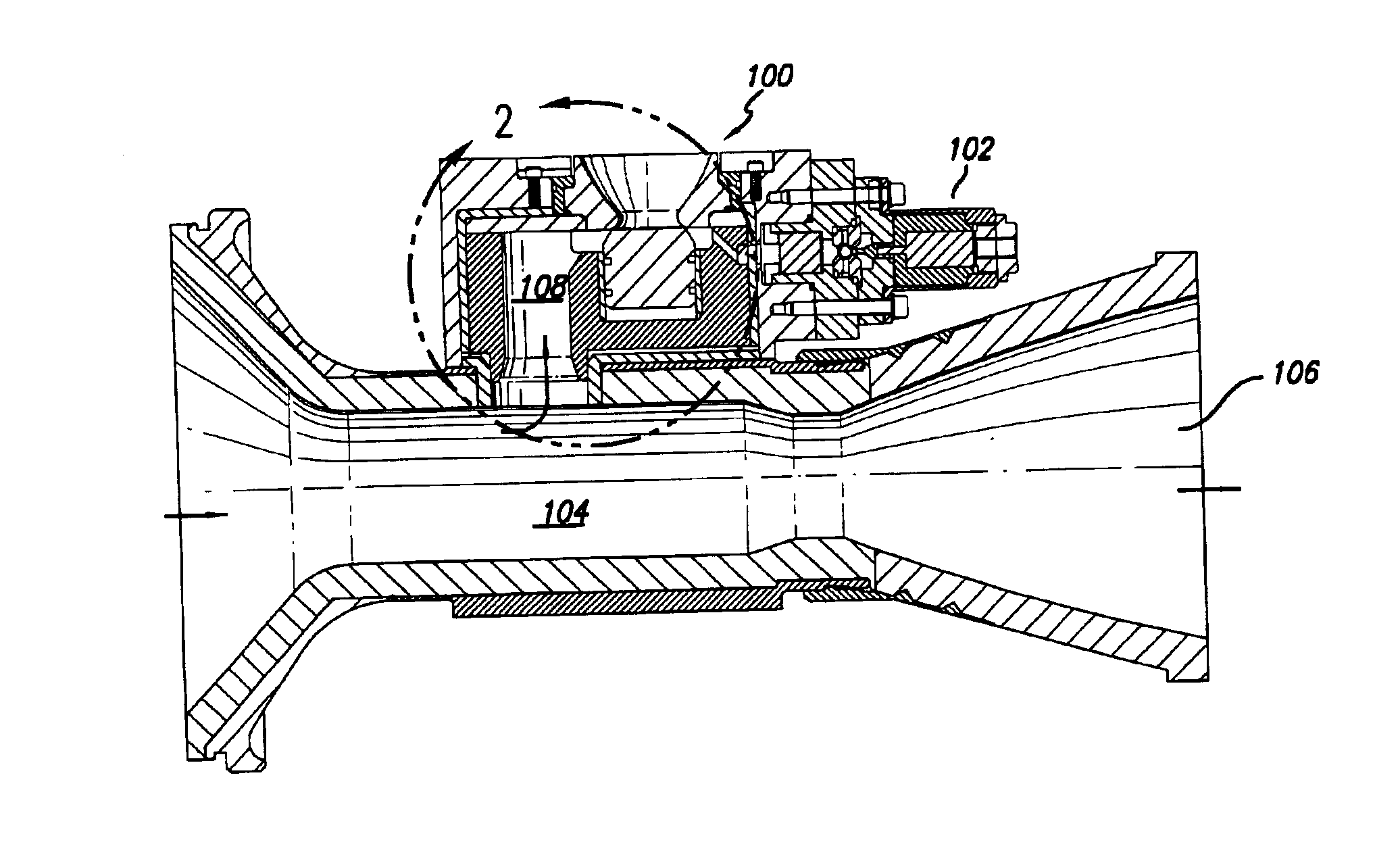
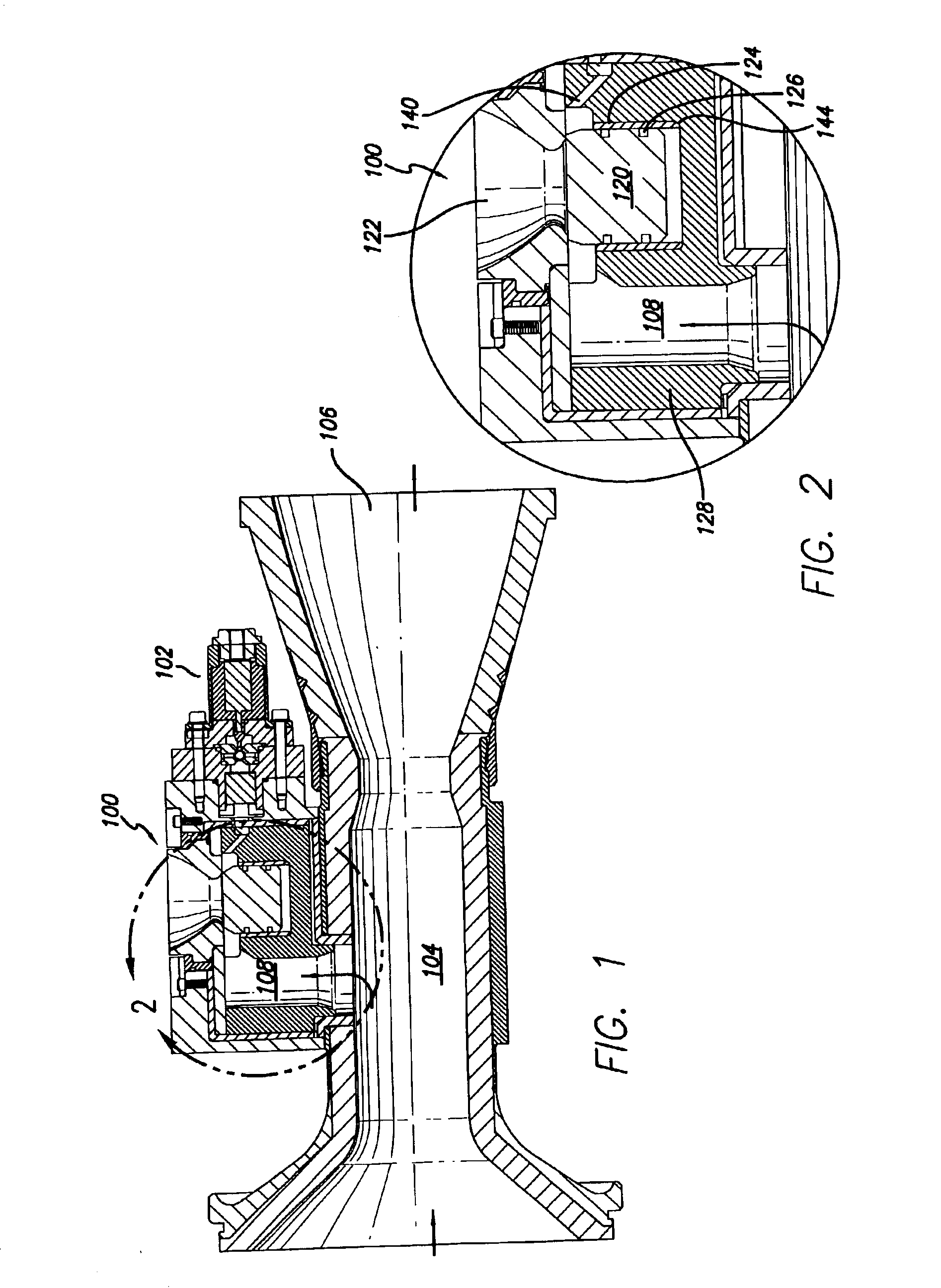
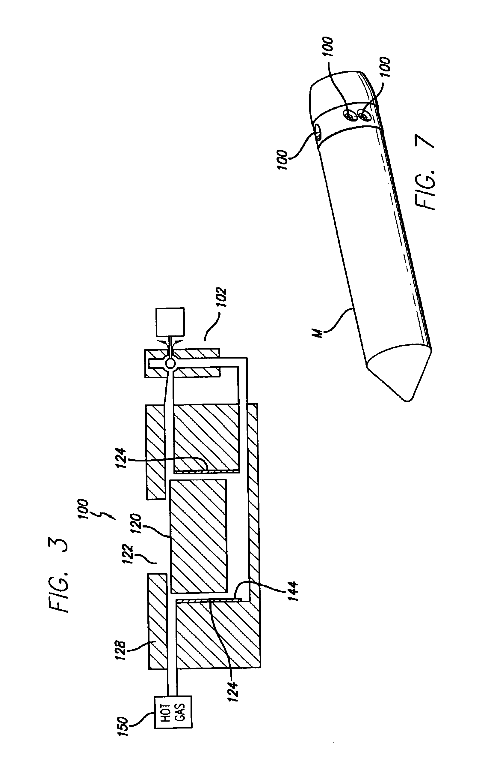
[0028]FIG. 1 shows in general schematic view the basic elements used in the gas valve with its refractory piston cylinder of the present invention. The valve 100 is coupled to a pilot valve 102 which generally controls the operation of the valve 100. In FIG. 1, hot gas is shown as flowing in from the left, passing through the throat 104 and exit...


PUM

PropertyMeasurementUnit
temperaturesaaaaaaaaaa
diametersaaaaaaaaaa

Abstract

An improved pneumatic valve and a missile with an improved thrust directional valve. In one embodiment, a refractory material lining for a pneumatic valve enables better valve operation and better valve performance. A thin-wall cylindrical sleeve of rhenium or other suitable refractory metal is located inside a cylinder. A valve piston may then travel within the refractory sleeve with greater reliability and better operation. The refractory sleeve cylinder lining can be subject to high temperatures at a rapid rate and remain operational. Under such a hostile environmental, including corrosive / erosive environments created by the passage of hot propellant gasses, the refractory cylinder sleeve has a more reliable operational life and is lighter in weight than conventional valves made entirely of refractory metals.

Description

CROSS-REFERENCES TO RELATED APPLICATIONS[0001]No priority is claimed from any other patent application.[0002]This application is related to a contemporaneously-filed patent for Vehicle and Lightweight Pneumatic Pilot Valve Therefor, Ser. No. 10 / 234,697 Honeywell International Incorporated, which is incorporated herein by reference.[0003]This patent application is related to U.S. patent application Ser. No. 10 / 138,090 filed May 3, 2002 entitled Oxidation and Wear Resistant Rhenium Metal Matrix Composite; U.S. patent application Ser. No. 10 / 138,087 filed May 3, 2002 entitled Oxidation Resistant Rhenium Alloys; U.S. Provisional Patent Application Ser. No. 60 / 384,631 filed May 31, 2002 entitled Use of Powdered Metal Sintering / Diffusion Bonding to Enable Applying Silicon Carbide or Rhenium Alloys to Face Seal Rotors; and U.S. Provisional Patent Application Ser. No. 60 / 384,737 filed May 31, 2002 entitled Reduced Temperature and Pressure Powder Metallurgy Process for Consolidating Rhenium ...

Claims


Application Information

Patent Timeline
Patent Type & Authority Patents(United States)
IPC IPC(8): F02K9/00F02K9/56F16L7/00
CPCF42B10/663Y10T137/7036
Inventor WOESSNER, GEORGE T.
Owner HONEYWELL INT INC
Why Eureka
Try Eureka