
Method and system to regulate cooling of a medical imaging device

Inactive Publication Date: 2005-06-21
GENERAL ELECTRIC CO
View PDF10 Cites 37 Cited by
  • Summary
  • Abstract
  • Description
  • Claims
  • Application Information

AI Technical Summary

Benefits of technology

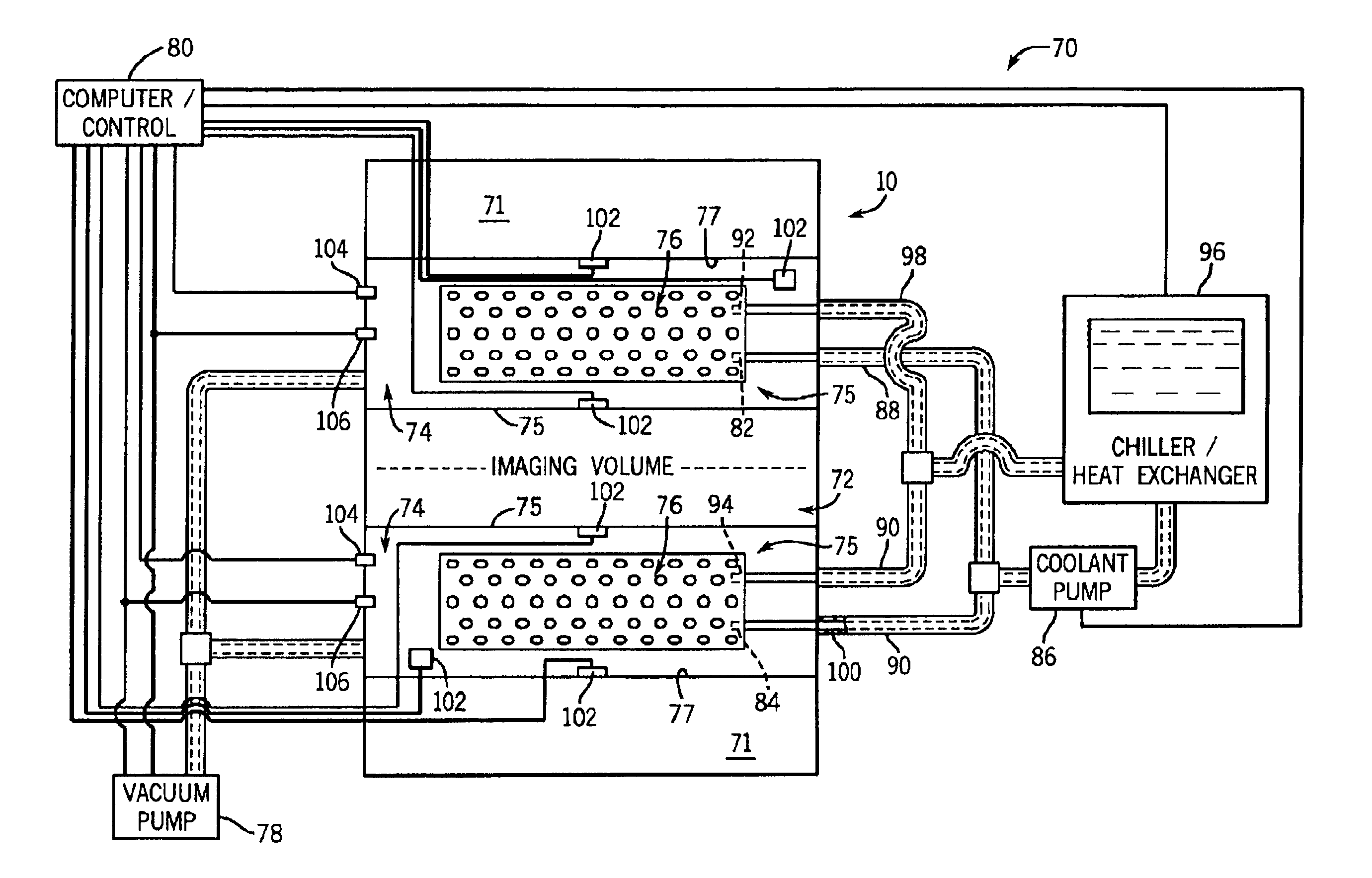
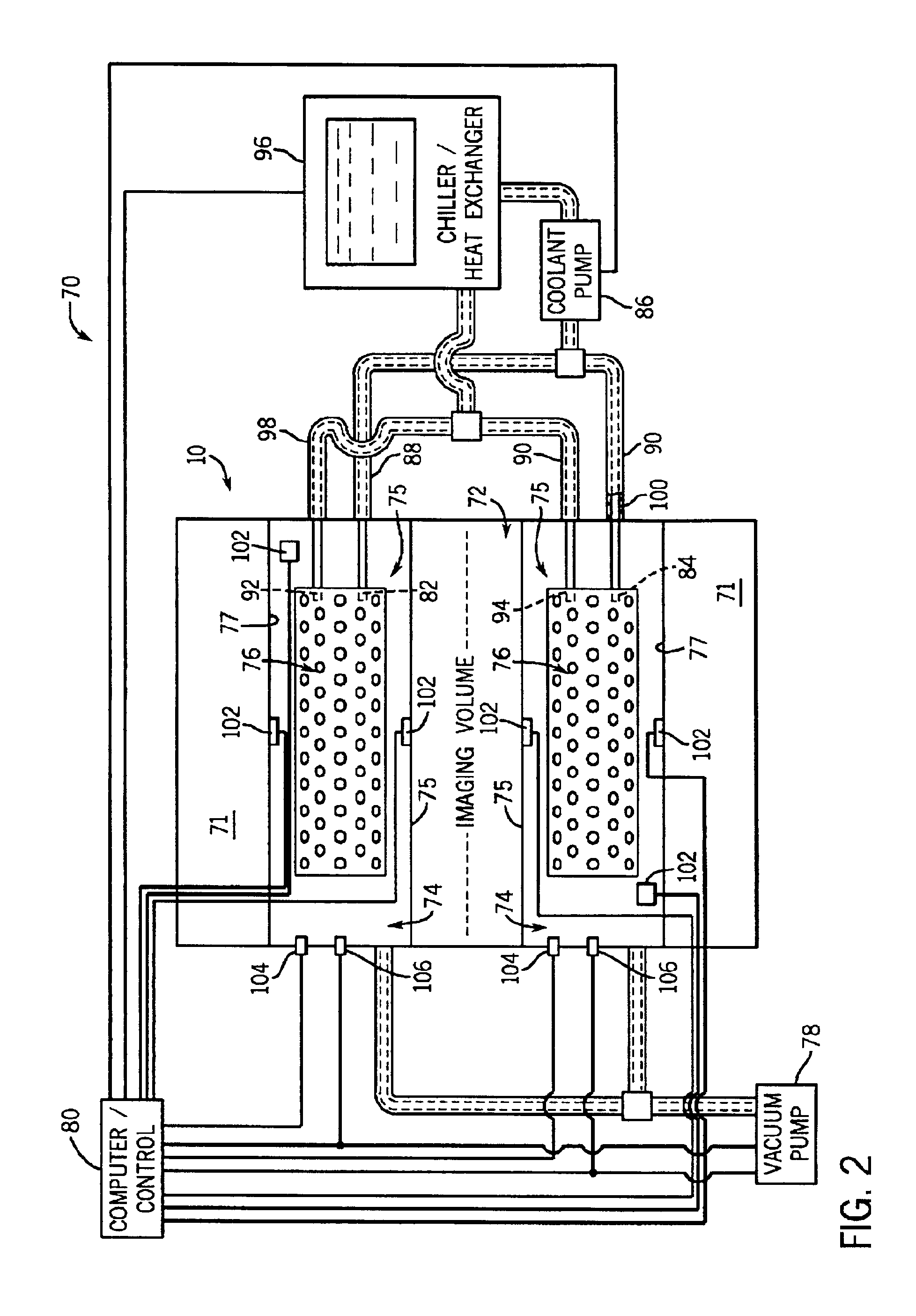
[0011]The present invention provides a system and method overcoming the aforementioned drawbacks by removing heat with lower coolant temperatures in a vacuum chamber containing the gradient and RF coils of an imaging device while maintaining internal and external temperatures below maximum operating limits, thereby enabling higher power applications for faster imaging with improved image quality, as well as, allowing longer scan times for interventional procedures.
[0012]A cooling system is provided with improved heat dissipation for an MRI resonance device. The cooling system includes a vacuum enclosure, a set of relative humidity, temperature and pressure sensors, and a control system that dynamically adjusts the temperature of coolant in cooling tubes embedded in the resonance module. The cooling fluid increases in temperature as it absorbs heat from the resonance module and transports the heat to a remote heat exchanger, such as, a water chiller. Since air and water vapor are removed from the vacuum enclosure containing the resonance module, condensation is prevented in the evacuated enclosure. As a result, the coolant temperature may be adjusted as needed to remove heat and maintain gradient coil temperatures within allowable levels.
[0013]Moreover, to further enhance proper operation and reliability, pressure and relative humidity sensors are placed in the vacuum enclosure to monitor for air and / or coolant leakage. To prevent condensation of water vapor on the exterior surfaces of the gradient coil, temperature sensors are installed on the patient and warm bore surfaces and in the vacuum enclosure. The control system is configured to provide the lowest practical coolant temperature while simultaneously preventing condensation on the patient and warm bore surfaces. Additionally, the relative humidity and pressure sensors may be used to trigger an alarm and disable the gradient coil drivers in response to an anomalous operating condition.

Problems solved by technology

In the resonance module, there are material temperature limitations, such as the glass transition temperature.
However, in current systems, the minimum temperature of the coolant supplied to the resonance modules is limited by the dew point temperature of the ambient air.
The maximum power which can be supplied to a resonance module is therefore limited by the external dew point temperature.
However, as indicated previously, environmental specifications limit the minimum coolant temperature to above 16° C. for an MR room with 75% relative humidity at 21° C. As a result, these current systems are unable to accommodate higher power patient scan sequences often required by resonance modules.
In case of increased temperatures of the resonance module or the patient surface, imaging scans must be interrupted or limited to low power sequences, which in turn reduces the efficiency and efficacy of the MR system.
Time is then lost because imaging sessions cannot begin anew until the resonance module or patient surface cools sufficiently.

Method used


Image

  • Method and system to regulate cooling of a medical imaging device
  • Method and system to regulate cooling of a medical imaging device
  • Method and system to regulate cooling of a medical imaging device

Examples


Embodiment Construction

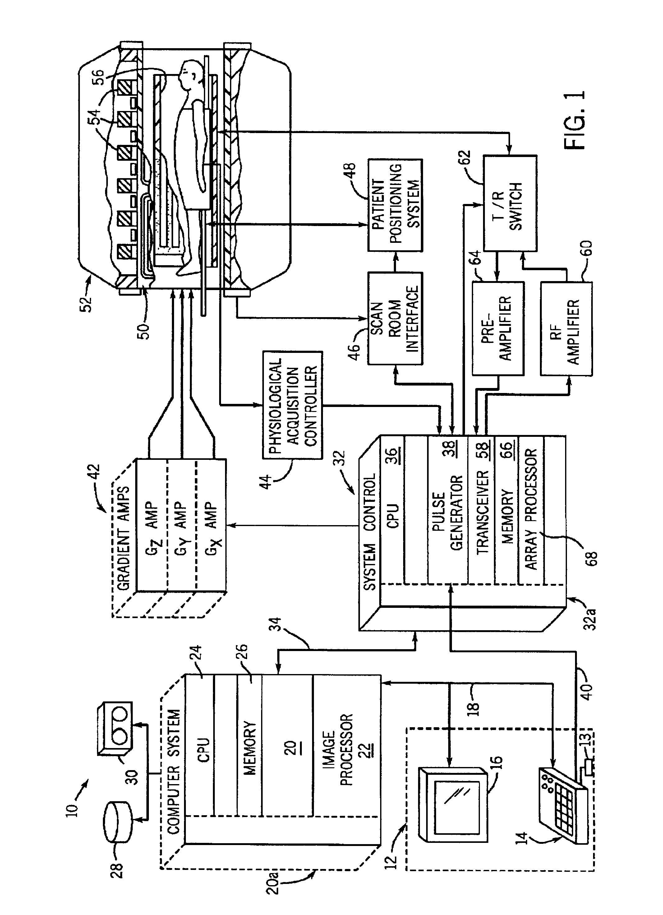
[0023]Referring to FIG. 1, the major components of a preferred magnetic resonance imaging (MRI) system 10 incorporating the present invention are shown. The operation of the system is controlled from an operator console 12 which includes a keyboard or other input device 13, a control panel 14, and a display 16. The console 12 communicates through a link 18 with a separate computer system 20 that enables an operator to control the production and display of images on the screen 16. The computer system 20 includes a number of modules which communicate with each other through a backplane 20a. These include an image processor module 22, a CPU module 24 and a memory module 26, known in the art as a frame buffer for storing image data arrays. The computer system 20 is linked to disk storage 28 and tape drive 30 for storage of image data and programs, and communicates with a separate system control 32 through a high speed serial link 34. The input device 13 can include a mouse, joystick, ke...


PUM


Abstract

The present invention provides a system and method of removing heat from an MR imaging device while maintaining internal and external temperatures below maximum operating limits, thereby enabling higher power applications for faster imaging with improved image quality as well as, allowing longer scan times for interventional procedures. The system includes a vacuum chamber housing the gradient coils and a vacuum pump connected thereto to regulate the pressure and humidity within the chamber. A heat exchanger, coolant pump, and controller are provided to regulate the temperature of coolant designed to dissipate heat from the gradient coils in response to at least one temperature sensor.

Description

BACKGROUND OF INVENTION[0001]The present invention relates generally to magnetic resonance imaging (MRI) apparatus, and more particularly to, a system and method to provide improved cooling to an MRI apparatus and thereby enable higher power applications for faster imaging with improved image quality and allow longer scan times.[0002]When a substance such as human tissue is subjected to a uniform magnetic field (polarizing field B0), the individual magnetic moments of the spins in the tissue attempt to align with this polarizing field, but precess about it in random order at their characteristic Larmor frequency. If the substance, or tissue, is subjected to a magnetic field (excitation field B1) which is in the x-y plane and which is near the Larmor frequency, the net aligned moment, or “longitudinal magnetization”, MZ, may be rotated, or “tipped”, into the x-y plane to produce a net transverse magnetic moment Mt. A signal is emitted by the excited spins after the excitation signal ...

Claims


Application Information

Patent Timeline
IPC IPC(8): G01R33/28G01R33/385A61B5/055
CPCG01R33/3856G01R33/28
Inventor EMERIC, PIERRE R.HEDLUND, CARL R.
Owner GENERAL ELECTRIC CO
Learn More