Fluorescent film with luminescent particles

Inactive Publication Date: 2005-06-28
SPECTROMETRIX OPTOELECTRONICS SYST
View PDF13 Cites 4 Cited by
  • Summary
  • Abstract
  • Description
  • Claims
  • Application Information

AI Technical Summary

Benefits of technology

[0024]An irradiation arrangement with very flexible handling can be constructed by arranging the fluorescent film outside the discharge space. For one, the life of the irradiation arrangement depends only upon the low-pressure discharge lamp itself, particularly its electrodes, sin

Problems solved by technology

While sapphire and quartz are transparent to UVC, it is not possible to use inorganic luminescent materials as a dopant in quartz windows for reasons p

Method used


Image

  • Fluorescent film with luminescent particles
  • Fluorescent film with luminescent particles
  • Fluorescent film with luminescent particles

Examples


Embodiment Construction

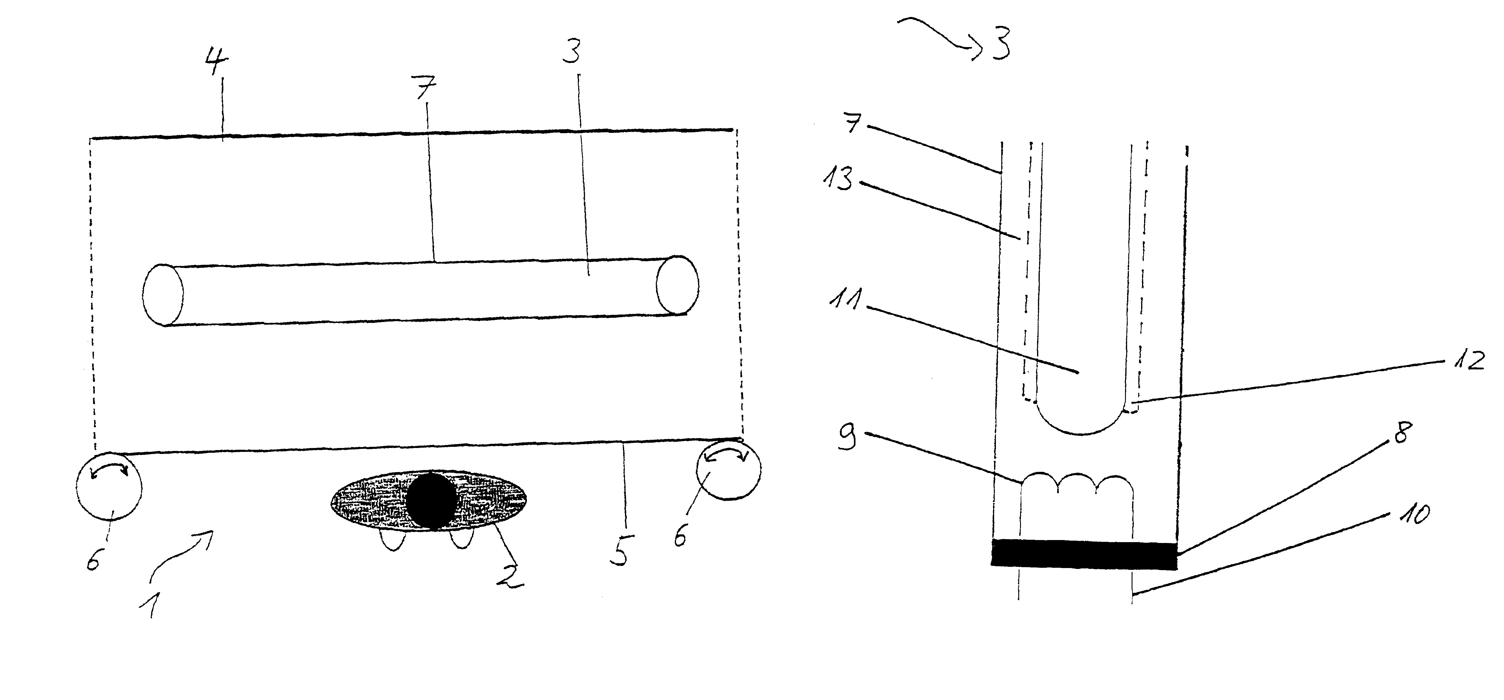
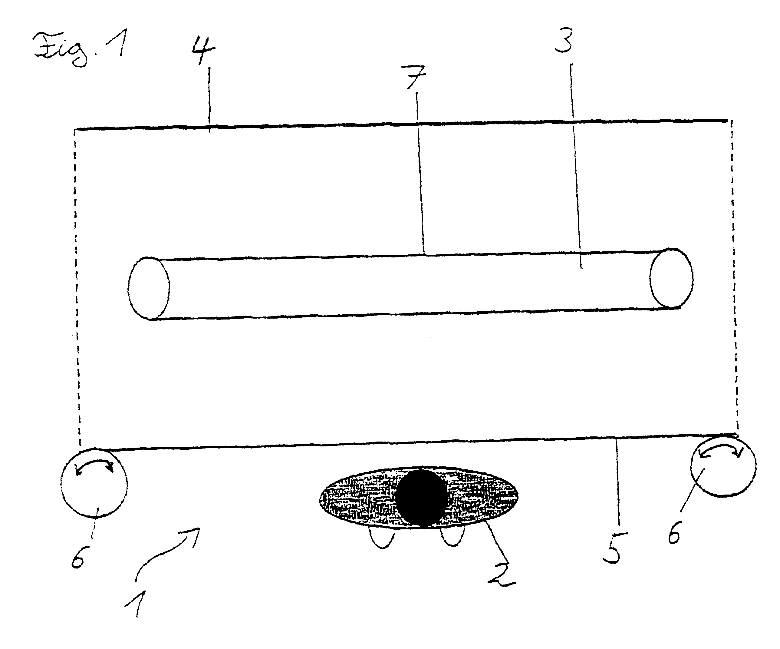
[0039]FIG. 1 shows a schematic top view of an irradiation arrangement 1 for cosmetic and / or therapeutic treatment of a patient 2. The irradiation arrangement 1 comprises at least one low-pressure discharge lamp 3, a reflector screen 4 and a fluorescent film 5 which is supported so that it can be wound on and off by means of rollers 6. The distances shown between the low-pressure discharge lamp 3 and the reflector screen 4 and fluorescent film 5 are not true to scale. The UV radiation generated in the discharge program of the low-pressure discharge lamp 3 exits isotropically from the UV-transparent enveloping tube 7 of the low-pressure discharge lamp 3 and impinges in part directly on the fluorescent film 5. Another portion of the radiation impinges on the reflector layer 4 and is partially reflected from the latter to the fluorescent film 5. The UV radiation impinging on the fluorescent film 5 partially excites the luminescent particles embedded in the fluorescent film 5 which then ...


PUM


Abstract

A fluorescent film for use with a low-pressure discharge lamp is formed as a silicone elastomer in which luminescent particles are embedded. The film is formed by the steps of (a) mixing a hydroxyl polydiorganosiloxane with an organohydrogen siloxane, (b) adding luminescent particles, and (c) generating a chemical reaction by means of a platinum catalyst at room temperature.

Description

[0001]This is a U.S. national stage of application No. PCT / DE00 / 03155, filed on 07 Sep. 2000. Priority under 35 U.S.C. §119(a) and 35 U.S.C. §365(b) is claimed from German Application No. 199 46 125.2, filed 20 Sep. 1999.BACKGROUND OF THE INVENTION[0002]1. Field of the Invention[0003]The invention is directed to a fluorescent foil or film, particularly for use with a low-pressure discharge lamp, a method for producing the fluorescent film and an irradiation arrangement with the fluorescent film.[0004]2. Description of the Related Art[0005]Light absorption through the skin causes tissue changes by influencing the neuronal, lymphatic, vascular and immune systems. This brings about analgesic, antiinflammatory, antiedematous effects and stimulates healing of wounds. A considerable increase in fibroblasts of scar tissue was found under irradiation by red light (660 nm, 2.4-4 J / cm2) (C. Webb; M. Dyson, et al., Lasers in Surgery and Medicine, 22(5), 294-30, (1998)). When peripheral lymphoc...

Claims


Application Information

Patent Timeline
IPC IPC(8): A61K41/00C09K11/02F21K2/00H01J61/46H01J61/38A61N5/06
CPCA61K41/0057H01J61/46F21K2/00C09K11/02A61N5/0616Y10T428/31663C09K11/08
Inventor CONRADY, JURGEN
Owner SPECTROMETRIX OPTOELECTRONICS SYST
Why Eureka
Try Eureka