
Method of manufacturing silicon carbide film

Active Publication Date: 2005-07-19
ASM JAPAN
View PDF30 Cites 19 Cited by
  • Summary
  • Abstract
  • Description
  • Claims
  • Application Information

AI Technical Summary

Benefits of technology

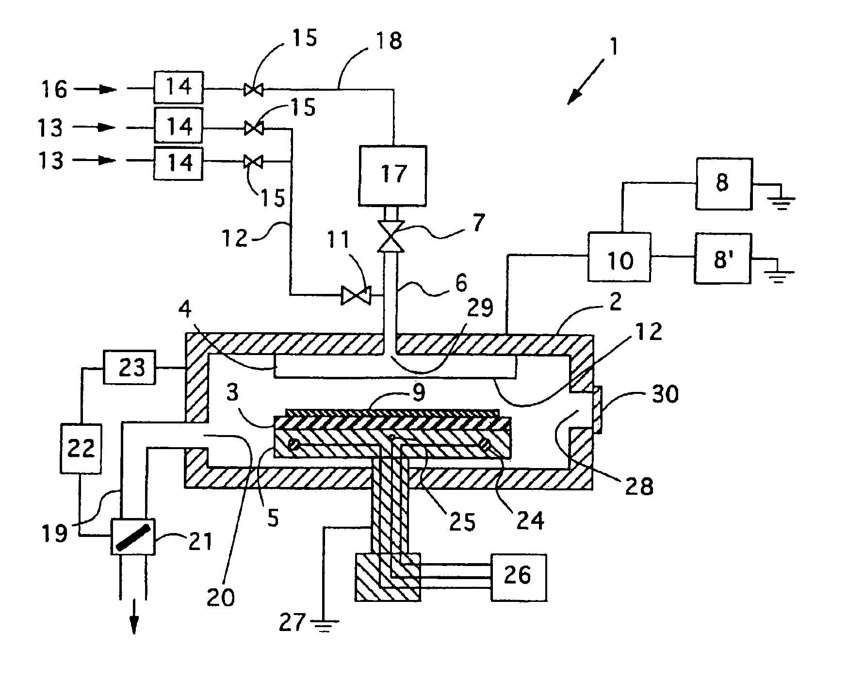
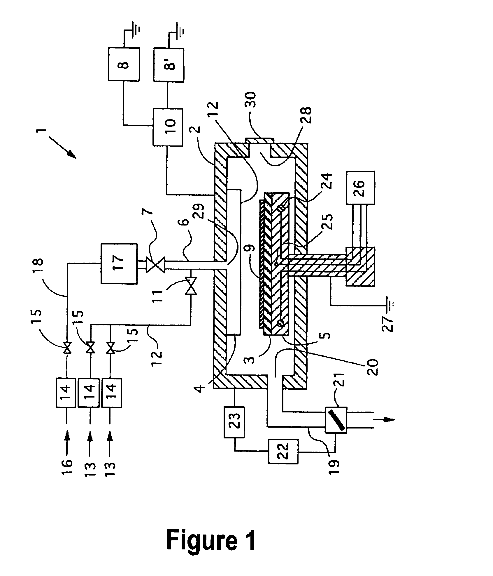
[0012]Consequently, an object of the present invention is to provide a method of manufacturing a silicon carbide film having a dielectric constant of about 4 or lower, whose film stress is not changed when it is left in the atmosphere, and which has low leakage current and a dry etching rate extremely lower than the carbon-containing silicon oxide film's and can be used as an etch stop film for copper wiring. Another object of the present invention is to provide a method of manufacturing a silicon carbide film having characteristics suitable for an etch stop film. Still another object of the present invention is to provide a method of manufacturing a silicon carbide film which is stable in the atmosphere and resistant to environmental changes, i.e., maintains its characteristics for a period of time sufficient for practical use. Still another object of the present invention is provide a method of manufacturing a silicon carbide film without complicated processes, preferably without discontinuing film formation processes, and at high efficiency. Yet another object of the present invention is to provide a method of manufacturing a silicon carbide film environmentally stabilized uniformly both in a thickness direction and in a diametrical direction. Still another object of the present invention is to provide a method of manufacturing a semiconductor device using a silicon carbide film as an etch stop layer. Further, another object of the present invention is to provide a method of forming copper wiring in a semiconductor device.

Problems solved by technology

Because a dielectric constant of the silicon nitride film, however, is approximately 7, which is high, a problem that the silicon nitride film increases interconnect capacity on the whole occurs even if the carbon-containing silicon oxide film is applied.
Additionally, the film has high leakage current and provides poor electrical isolation.
This method, however, only improves the quality of the very surface of the film; it does not improve internal characteristics of the SiCH film; the film still has high leakage current and provides poor electrical isolation.
The dielectric constant of this film is approximately 4.5 to 5; hence application of the film to current LSI devices aiming to perform faster is difficult.
The silicon carbide films have a problem, however, that due to their chemical properties similar to a carbon-containing silicon oxide film, their etching rate difference with the carbon-containing silicon oxide film's becomes small (within 3 to 4 times), lowering their etch stop performance.
Particularly, because the SiCOH film whose dielectric constant is lowered by increasing its oxygen content has a chemical composition similar to the carbon-containing silicon oxide film which is used as an insulating film for the interconnects, it is etched at a rate close to an etching rate of the carbon-containing silicon oxide film, making difficult to form vias or trenches for copper wiring to be formed by Reactive Ion Etching (RIE) using C4F8+O2+Ar gas.

Method used


Image

  • Method of manufacturing silicon carbide film
  • Method of manufacturing silicon carbide film
  • Method of manufacturing silicon carbide film

Examples


example 1

4) Example 1 Sequence F

First Deposition Step:

[0070]

Deposi-ReactiontionTMSHeChamberTemp.Flow RateFlow RatePressure27.12 MHz400 kHz330° C.300 sccm500 sccm600 Pa400 W150 W

Second Deposition Step (Execution time: 8 seconds):

[0071]

Deposi-ReactiontionTMSHePressureTemp.Flow RateFlow RateChamber27.12 MHz400 kHz330° C.0 sccm2,500 sccm600 Pa400 W150 W

5) Example 2 Sequence F; Ar was Used as an Inert Gas

First Deposition Step:

[0072]

Deposi-ReactiontionTMSArChamberTemp.Flow RateFlow RatePressure27.12 MHz400 kHz330° C.300 sccm500 sccm600 Pa400 W150 W

Second Deposition Step (Execution time: 8 seconds):

[0073]

Deposi-ReactiontionTMSArChamberTemp.Flow RateFlow RatePressure27.12 MHz400 kHz330° C.0 sccm2,500 sccm600 Pa400 W150 W

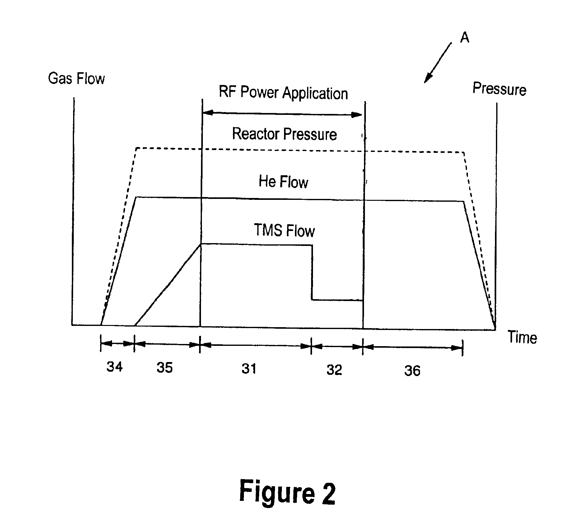
[0074]In Examples 1 and 2, Sequence F was applied which is shown in FIG. 7. That is, the flow rate of the raw material gas was discontinuously increased, whereas the flow rate of the inert gas was continuously decreased to zero. As with the other figures, the axes of FIG. 7 are not a...


PUM

PropertyMeasurementUnit
Temperatureaaaaaaaaaa
Timeaaaaaaaaaa
Thicknessaaaaaaaaaa

Abstract

A method for forming a silicon carbide film on a semiconductor substrate by plasma CVD includes (a) introducing a raw material gas containing silicon, carbon, and hydrogen and an inert gas into a reaction chamber at a predetermined mixture ratio of the raw material gas to the inert gas; (b) applying radio-frequency power at the mixture ratio, thereby forming a curable silicon carbide film having a dielectric constant of about 4.0 or higher; and (c) continuously applying radio-frequency power at a mixture ratio which is reduced from that in step (b), thereby curing the silicon carbide film to give a dielectric constant lower than that of the curable silicon carbide film.

Description

BACKGROUND OF THE INVENTION[0001]1. Field of the Invention[0002]The present invention relates to a deposition method by plasma CVD. More particularly, the present invention relates to a silicon carbide film which acts as an etch stop film used for copper wiring.[0003]2. Description of the Related Art[0004]Conventionally, in LSI devices including CPUs, memories, system LSIs, aluminum alloy has been used for metal interconnects. To insulate aluminum interconnects, a silicon oxide film is used; for some LSI devices, a fluorine-containing silicon oxide film is used.[0005]In recent years, copper which has lower electrical resistivity than aluminum has been adopted as a material for metal wiring to speed up LSI devices'performance, and a carbon-containing silicon oxide film having a low dielectric constant has started to be adopted as an interlayer insulating film to reduce interconnect capacity which causes signal delay. In an LSI device having this copper wiring, an etch stop film is us...

Claims


Application Information

Patent Timeline
IPC IPC(8): C23C16/32H01L21/768H01L21/70C23C16/44H01L21/3065C23C16/455H01L21/314
CPCC23C16/325C23C16/45523H01L21/76828H01L21/76829
Inventor SATOH, KIYOSHIGOUNDAR, KAMAL KISHORE
Owner ASM JAPAN
Learn More