High-speed electromechanical shutter for imaging spectrographs

Inactive Publication Date: 2005-08-30
NASA
View PDF20 Cites 27 Cited by
  • Summary
  • Abstract
  • Description
  • Claims
  • Application Information

AI Technical Summary

Benefits of technology

[0008]It is an object of the invention to provide a clear aperture of at least 0.5 mm×10 mm which is the typical entrance slit on spectrographs and good optical throughput or transmission with excellent imaging capability.
[0009]It is another object of the invention to provide a robust design that is easy to use and requires minimal maintenance. This is achieved by electronically coupling the chopper blades so as to avoid complex, and potentially troublesome mechanical coupling mechanisms. Further, it is another object of the invention to use relatively low speed (i.e. 4,000 to 8,000, and preferably about 6,000 rpm) motors that are commercially available as off the shelf items. This helps to meet another object of the invention of avoiding issues with dynamic balance and vibration and other safety concerns related to the use of high speed rotating equipment.

Problems solved by technology

However, this use in particular often suffers from large sources of background interference such as flame and soot luminosity that are substantially brighter than the faint amounts of signals derived form the weak Raman effect.
Problems encountered with some of these prior art techniques include low quantum efficiency, decreased signal to noise ratio (SNR), and a low dynamic range of about 102, or 103 at best.
However, non-intensified CCD's do not have the ability to gate-out background light interference on the time scale of the laser pulse resulting in large background signal levels.
The use of FLC's however, was only marginally better than the use of intensified CCD's due to the FLC's reduced optical efficiency and wider temporal gate width.
However, these prior art techniques suffer from being complex and difficult to build and maintain at the desired speed of operation.

Method used


Image

  • High-speed electromechanical shutter for imaging spectrographs
  • High-speed electromechanical shutter for imaging spectrographs
  • High-speed electromechanical shutter for imaging spectrographs

Examples


Embodiment Construction

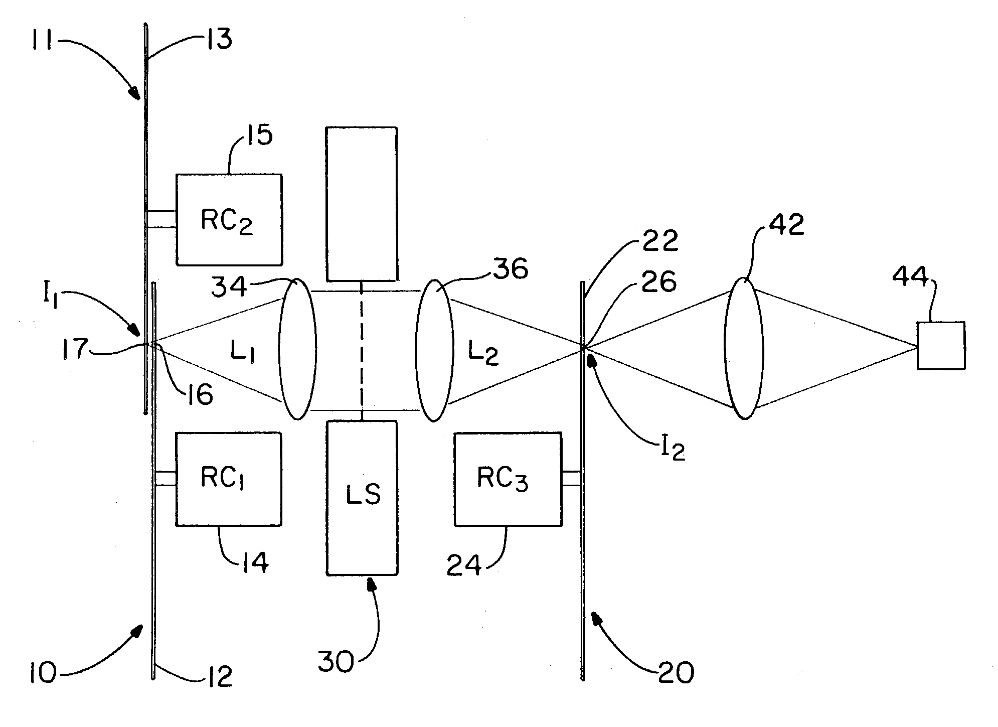
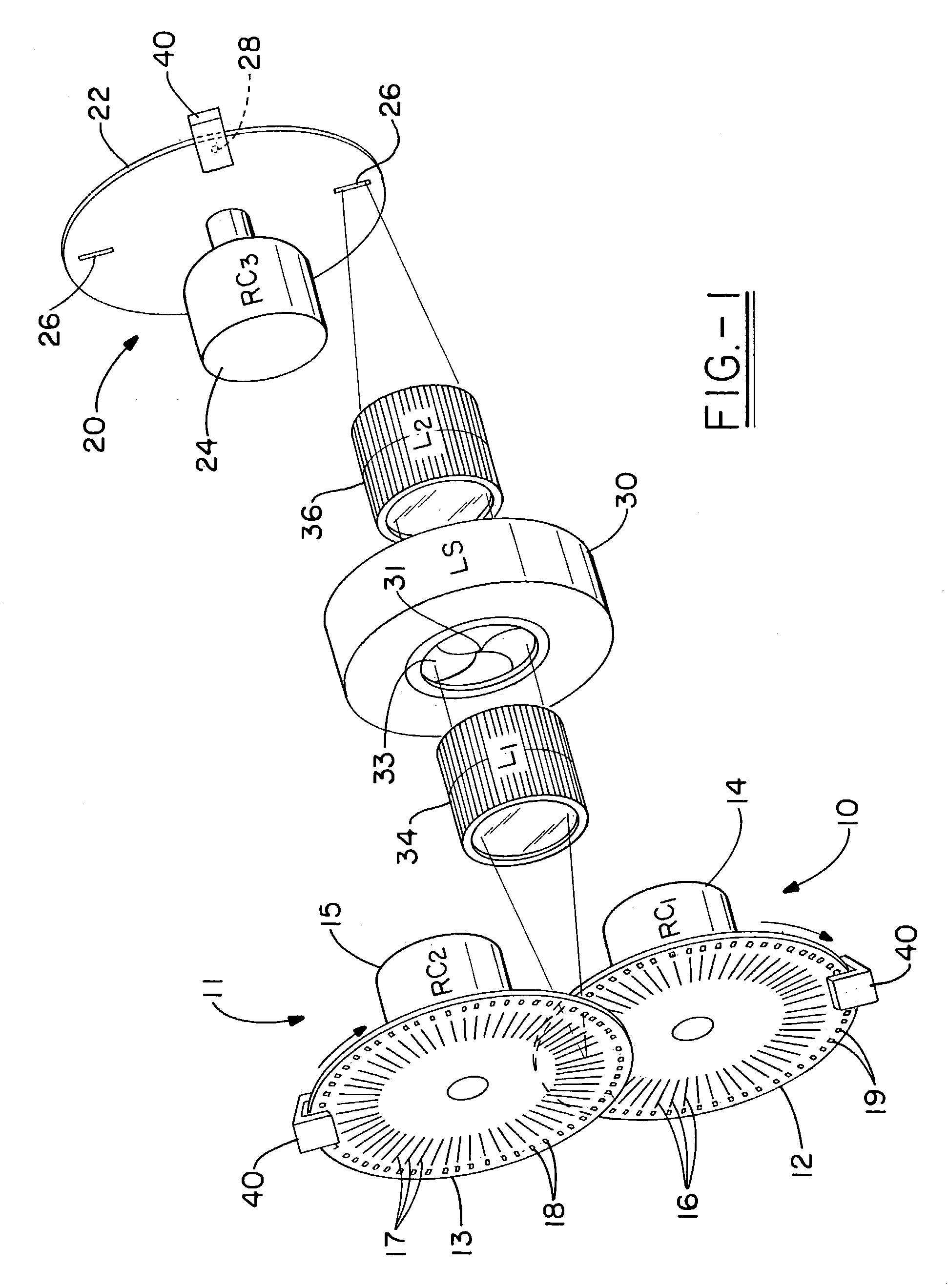
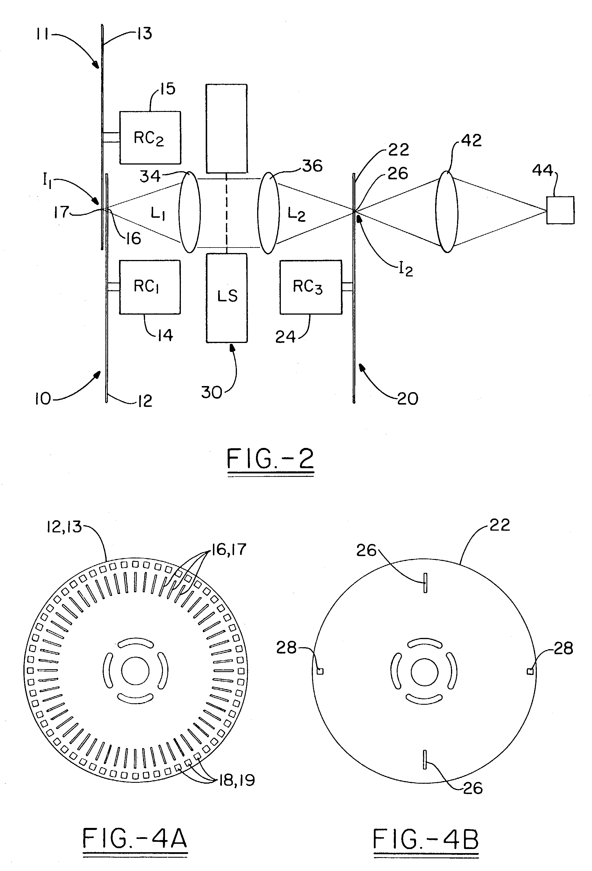
[0032]The high speed electromechanical shutter in accordance with the present invention is shown generally in FIG. 1 and shown as a schematic in FIG. 2. The invention uses a set of three low speed (i.e. about 6,000 RPM) electronically phase-locked rotary choppers in conjunction with a conventional reciprocating shutter, such as a leaf or blade shutter, or even a oscillating shutter, such as a butterfly shutter. By using solid state electronics to gear the choppers together, the choppers act in synchronism with a number of benefits: the motors are available as off the shelf items, the invention eliminates complex and unreliable mechanical gearing, and the speed of the motors is relatively benign.

[0033]The invention comprises a set of rotary choppers including a first 10 and a second 11 rotary chopper each having rotary blade or disc 12, 13, respectively coupled to its own motor 14, 15 and each having a plurality of peripheral optical slots 16, 17 and a corresponding plurality of phas...


PUM


Abstract

The present invention presents a high-speed electromechanical shutter which has at least two rotary beam choppers that are synchronized using a phase-locked loop electronic control to reduce the duty cycle. These choppers have blade means that can comprise discs or drums, each having about 60 (+ / −15) slots which are from about 0.3 to about 0.8 mm wide and about 5 to about 20 mm long (radially) which are evenly distributed through out 360°, and a third rotary chopper which is optically aligned has a small number of slots, such as for example, 1 to 10 slots which are about 1 to about 2 mm wide and about 5 to about 20 mm long (radially). Further the blade means include phase slots that allow the blade means to be phase locked using a closed loop control circuit. In addition, in a preferred embodiment, the system also has a leaf shutter. Thus the invention preferably achieves a gate width of less than about 100 microseconds, using motors that operate at 3000 to 10,000 rpm, and with a phase jitter of less than about 1.5 microseconds, and further using an aperture with more than about 75% optical transmission with a clear aperture of about 0.8 mm×10 mm. The system can be synchronized to external sources at 0 6 kHz lasers, data acquisition systems, and cameras.

Description

[0001]The invention relates generally to high-speed shutter mechanisms, and in particular, to high-speed shutter mechanisms which can be used to enhance the use of spectrometers by diminishing background light. The current invention provides an ultra high speed shutter in which multiple shutter mechanisms are electronically coupled using phase locked loop electronic control so as avoid the use of ultra high speed motors or complicated gearing mechanisms. This solution to the issue of high speed gating achieves a repetition rate ranging from 1 Hz to 6 kHz, which is ideal for use with a pulsed laser having typical repetition rates within this range, such as a 10 Hz Nd:YAG laser. The system can achieve a gate width of about 20 microseconds or less with an accuracy of + / −1.5 μs (phase jitter). The system is simple, and mechanically robust, easy to align, and relatively safe and easy to use.BACKGROUND OF THE INVENTION[0002]Sophisticated analytical techniques of the present day include th...

Claims


Application Information

Patent Timeline
IPC IPC(8): G01J3/40G01J3/28
CPCG01J3/2823G01J3/0232
Inventor NGUYEN, QUANG-VIET
Owner NASA
Why Eureka
Try Eureka