
Rapid infusion system

Inactive Publication Date: 2005-09-13
SMISSON CARTLEDGE BIOMEDICAL
View PDF32 Cites 90 Cited by
  • Summary
  • Abstract
  • Description
  • Claims
  • Application Information

AI Technical Summary

Benefits of technology

[0019]Another advantage of the present invention is an integrated motor drive that allows the device to deliver a wide range of flow rates of fluids from a unit that is small and compact. In addition, the present invention provides a wide variety of flow rates with no change in the configuration of the drive system.
[0020]Another advantage of the present invention is the pump chamber and drip chamber are in one disposable unit that is easily installed by the operator of the device. All of these unique features provide a rapid infusion system that is (1) small, light-weight and relatively inexpensive because of the simple design of the device; (2) flexible because the device can deliver wide ranges of flow rates of fluids without the need to change the configuration of the drive system; (3) safe because the possibility of air entering the delivery tubing is virtually eliminated; and (4) easy to use because the pump chamber and the drip chamber are in one, easily installed unit. The present invention is capable of rapidly delivering fluids with greatly reduced operational demands to a patient suffering from acute hypovoleria. The rapid infusion system offers improved mechanical functions and desirable operational improvements over previously known systems and practices in the management of critical, life- threatening situations.
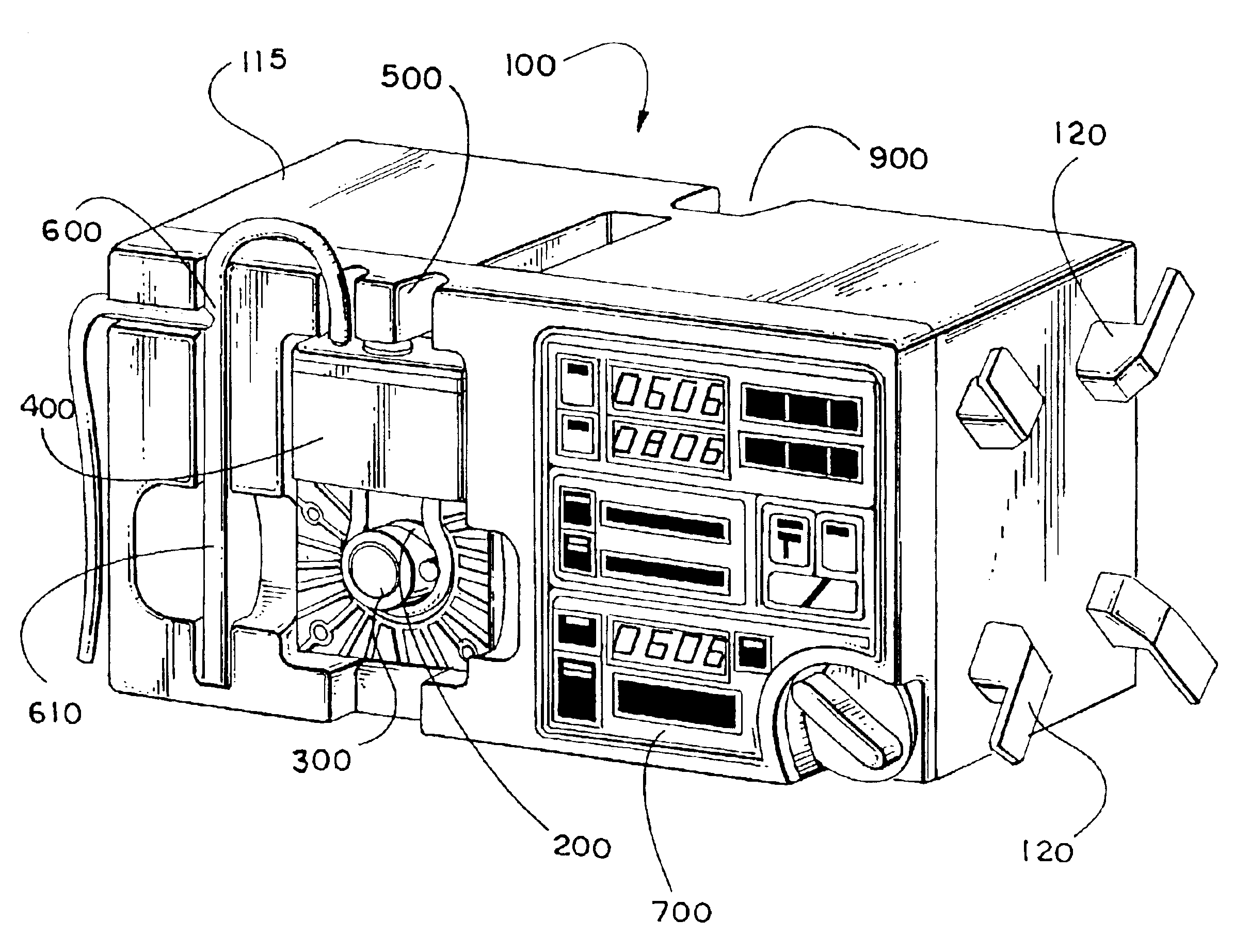
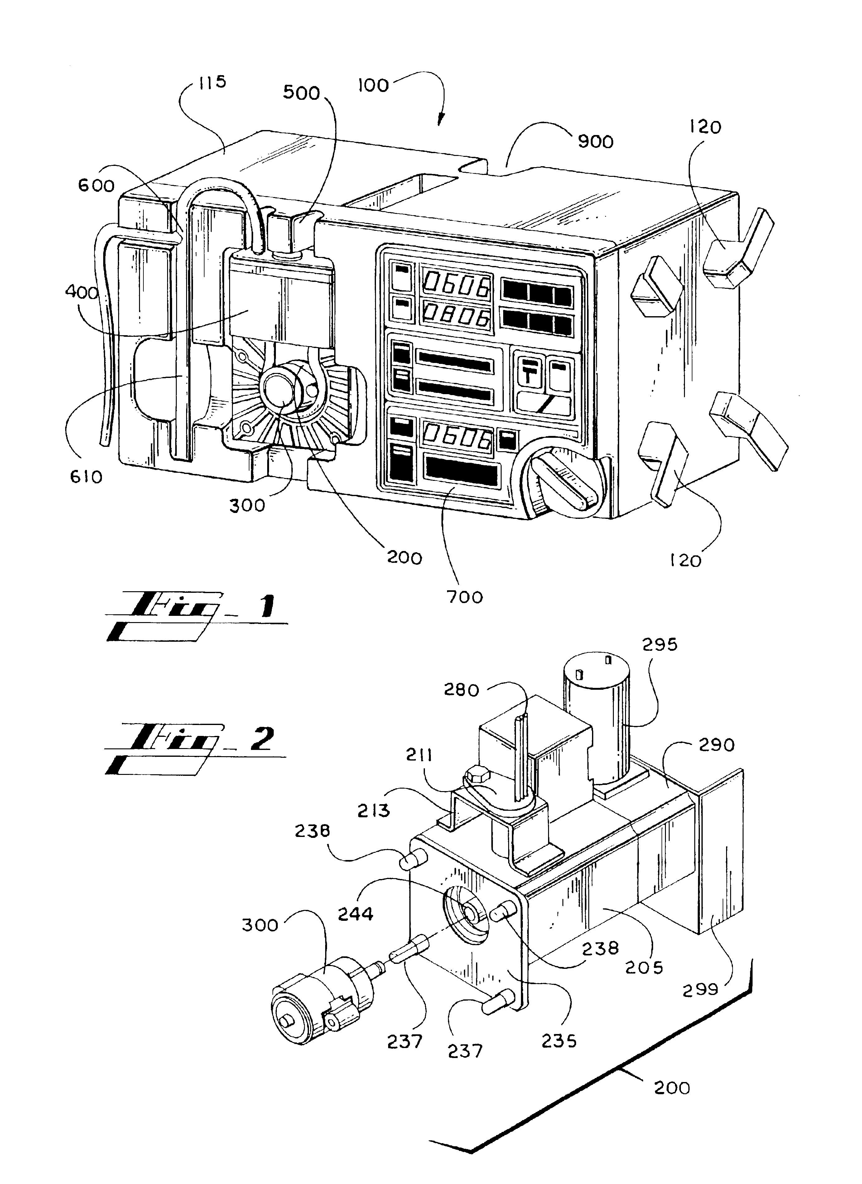
[0021]In one preferred embodiment, the rapid infusion system includes a pump assembly, a drive assembly to power the pump, and a fluid containment system that keeps the infused fluid out of direct contact with the pump assembly and that is preferably disposable and removable. The system optionally includes components such as a pressure sensor and controller, a temperature sensor and controller, a filter to remove any occlusive material from the fluid, an automatic self-leveling system to keep the fluid in the drip chamber at an appropriate level for maximal delivery efficiency, and a sensor system to detect the presence of air bubbles in the fluid in conjunction with a switch that can stop the flow in the conduit in response to a detected air bubble of a dangerous size.
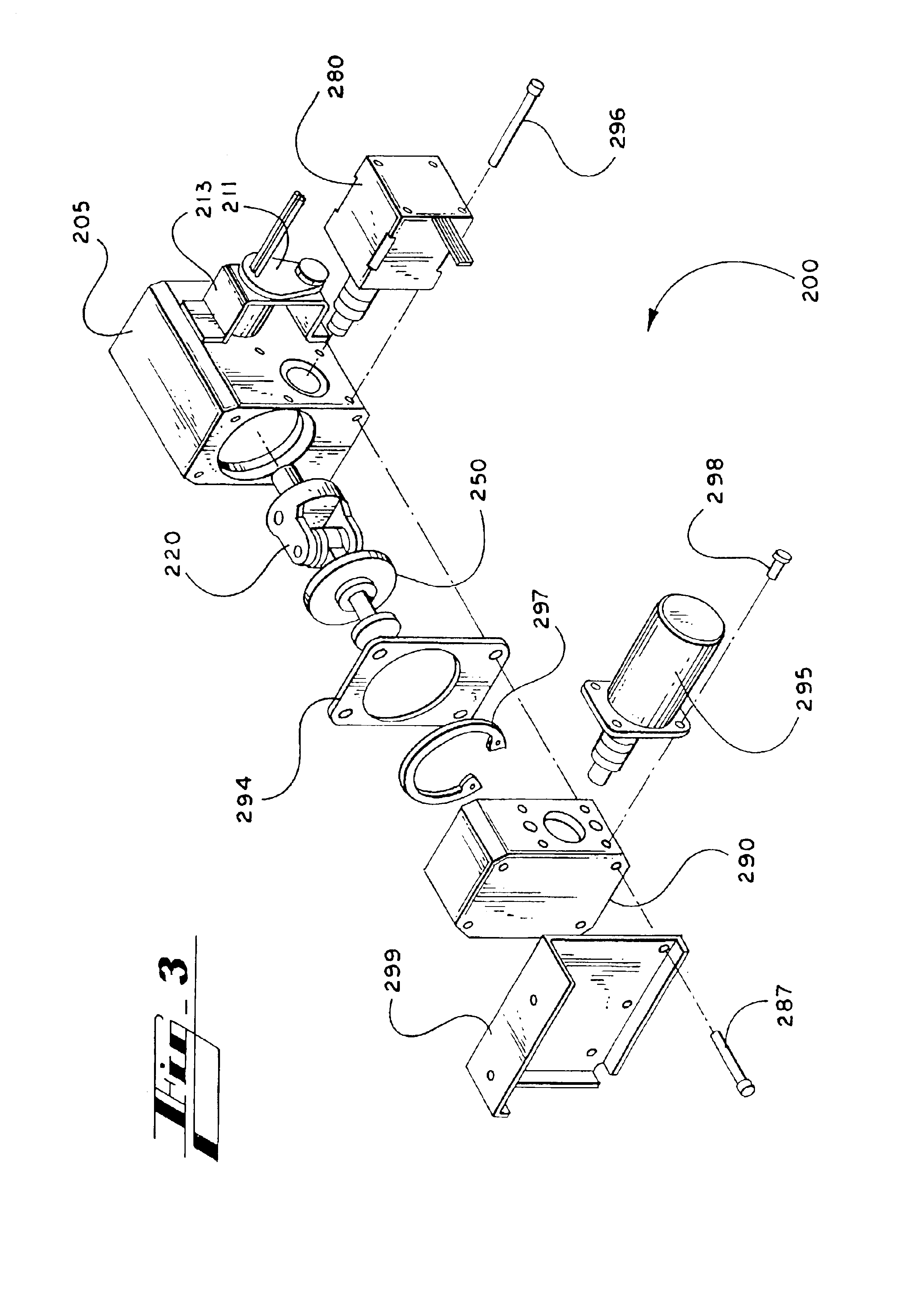
[0022]The flow rate of the pump advantageously is continuously adjustable and, preferably, can provide fluid flow rates from less than 20 cc / hour to more than 1,500 cc / minute. In a preferred embodiment, the pump is a roller pump and is connected with a drive assembly using a differential assembly to provide seamless transition from standard flow rates to high flow rates.
[0023]The present system provides a cost effective, yet safe method of handling sterile infusions, as all components of the system that physically contact the infused fluid are contained within or attached to a sterile, disposable cartridge designed for single use. In one embodiment, the single use pump cartridge includes a section of pre-formed tubing serving as the pump chamber. The cartridge includes a drip chamber that is self-leveling. Optionally, the system may include a temperature sensor at the output of the temperature controller for measuring and adjusting the fluid temperature to maintain the temperature within acceptable limits. Other embodiments of the system may also incorporate other monitoring sensors and feedback devices to allow adjustments to be made by the infusion system in response to physiologic measurements, such as central venous pressure, pulmonary arterial wedge pressure, urine output, pulse, mean arterial blood pressure, and similar parameters. Still other embodiments of the system may incorporate other monitoring sensors and feedback devices to allow either quantitative or qualitative adjustments in the infusium in response to in vivo sensors measuring parameters such as arterial pH, serum potassium, serum glucose, and other physiologic or chemical factors. The system also preferably includes a user display, which displays parameters including fluid temperature, line pressure, fluid flow rate, and total volume of fluid infused.
[0024]A further advantage of this system is that it does not require dedicated technical personnel for its operation, and it can readily be programmed and operated by nursing or emergency personnel in the course of their other patient care duties. Yet another advantage of this system is an electronic control system that allows precise, in vivo monitoring of blood pressure and / or chemistries, and the system may be programmed to make precise and automatic adjustments of the infusion rate to the patient based upon the monitored parameters.

Problems solved by technology

In the past, the replacement of large amounts of fluids has been a major problem to the medical or surgical teams attending a patient with these acute needs.
This method may be limited by the number of peripheral or central sites that can be physically accessed in a given patient, the number of people attending the fluids being infused, as well as the efficiency of infusing the fluids during a dire, hypovolemic event.
While the potential need for rapid infusion is present in a number of common clinical situations, the actual need is unpredictable and may arise suddenly during the course of treatment or surgery.
A high C.V.P. is an indication of volume overload and can result in heart failure and pulmonary edema (or fluid) in the lungs.
It appears that the pumps can provide only routine infusion rates.
Most prior art infusion pumps are designed for medication delivery and are limited in their performance to the routine range of infusion rates.
Such pumps are not capable of rapid intravenous infusion.
Although some prior art infusion systems can deliver rapid infusion, those prior art rapid infusion devices are physically large, complex systems that require dedicated operation by skilled technicians.

Method used


Image

  • Rapid infusion system
  • Rapid infusion system
  • Rapid infusion system

Examples


Embodiment Construction

[0058]A system for rapid, intravenous infusion of a fluid is disclosed. The term “fluid” as used herein refers to blood, plasma, platelets, cryoprecipitates, blood products, physiologic fluids, medications, and other blood products and blood components. The system includes a drip chamber having an intake port for receiving the fluid and an outlet port for dispensing the fluid. The drip chamber is preferably included in a pump cartridge that may also include the pump chamber. A pump assembly propels the fluid through the system, and can include a gear pump, a turbine pump, a roller head occlusive pump, a nonocclusive centrifugal pump, or the like. The pump advantageously is adjustable and can provide fluid flow rates from less than 20 cc / hour to more than 1500 cc / minute.

[0059]The system further includes a drive assembly for driving the pump and one or more motors for powering the drive. Optionally, the system can include a fluid temperature controller, one or more optional filters to...


PUM


Abstract

A rapid infusion system for the intravenous delivery of fluids at standard and rapid flow rates. The system includes a pump assembly, a drive assembly to power the pump, and a fluid containment system that keeps the infused fluid out of direct contact with the pump assembly and that is preferably disposable and removable. In one embodiment the drive assembly includes a differential drive that interacts with more than one motor. In one embodiment, the pump assembly includes a roller pump and the pump chamber is a collapsible, preformed tube that is preferably attached to a pump cartridge frame. Optionally, the system includes a self-leveling drip chamber and the fluid containment system is disposable and includes a pump cartridge containing the drip chamber and the pump chamber, I.V. tubing, outlet infusion tubing, and a heater cartridge.

Description

RELATED APPLICATION[0001]This application is a continuation of U.S. Ser. No. 09 / 510,139 filed Feb. 22, 2000 now U.S. Pat. No. 6,554,791, which claims priority to U.S. Provisional Application No. 60 / 156,674 filed Sep. 29, 1999.FIELD OF THE INVENTION[0002]The invention relates to medical devices and methods for the infusion of fluids such as blood, blood products, and medications into a patient requiring circulatory volume replacement, with a capability for infusion over a range from slow to extremely rapid flow rates.BACKGROUND OF THE INVENTION[0003]A variety of clinical circumstances, including massive trauma, major surgical procedures, massive burns, and certain disease states such as pancreatitis and diabetic ketoacidosis can produce profound circulatory volume depletion, either from actual blood loss or from internal fluid imbalance. In these clinical settings, it is frequently necessary to infuse blood or other fluids rapidly into a patient to avert serious consequences.[0004]In...

Claims


Application Information

Patent Timeline
IPC IPC(8): A61M1/02A61M5/142F04B43/12A61K9/22
CPCA61M1/02A61M5/1411A61M5/142A61M5/14232A61M5/365F04B43/1253A61M5/14244A61M2205/12
Inventor CARTLEDGE, RICHARD G.SMISSON, III, HUGH F.BROWN, JEFFERY O.
Owner SMISSON CARTLEDGE BIOMEDICAL
Learn More