Semiconductor memories

a technology of memory and semiconductors, applied in semiconductor devices, digital storage, instruments, etc., can solve the problems of reducing the area required by the peripheral circuit of memory arrays, and achieve the effects of reducing the size of memory cells, and increasing the retention tim

Inactive Publication Date: 2005-09-27
HITACHI LTD
View PDF4 Cites 37 Cited by
  • Summary
  • Abstract
  • Description
  • Claims
  • Application Information

AI Technical Summary

Benefits of technology

[0010]A semiconductor memory cell may achieve a smaller area by sharing the reference node between adjacent cells. In addition, since a constant voltage is written to the storage node, an additional voltage boost circuit for the word line becomes unnecessary, thus reducing the area required by the memory array peripheral circuits. This technique is used in several 2T and 3T memory cell structures presented according to the present invention.
[0012]According to the present invention, a memory is provided in which the memory cell combines the fixed voltage reference node writing method with the thin-channel charge transfer transistor to achieve a high-density, low-power dynamic memory. This memory cell may be fabricated in a 2-T configuration with a double-gate readout transistor and a 3-T cell in which separate storage and read transistors are included in each cell. In addition, a memory derived from the 2-T cell with series-connected memory cells arranged in subcolumns or parallel-connected memory cells arranged in subcolumns is also provided. The present invention results in a density approaching or surpassing that of conventional DRAM memories. Also, memory cells of this type, with an additional capacitive element to increase retention time, are also provided.
[0013]In at least one embodiment, a memory comprises a thin-channel transistor used in a memory cell in a four-transistor (4-T) configuration that exhibits a static operation. The memory cell preferably has two access transistors and two thin-channel transistors in a cross-coupling, self-restoring configuration. If the source-drain leakage current from the data line through the bulk transistor is higher than the leakage current from the storage node, a stable memory can be realized, obviating the need for a refresh operation. In addition, the thin-channel transistors may be fabricated in a much smaller area than bulk transistors, realizing a drastically reduced memory cell size. In a further embodiment, a separate two-transistor readout circuit is included in each cell to overcome the slow read time of the four-transistor cell. In this manner, a low power, high-speed memory cell is presented.

Problems solved by technology

In addition, since a constant voltage is written to the storage node, an additional voltage boost circuit for the word line becomes unnecessary, thus reducing the area required by the memory array peripheral circuits.

Method used


Image

  • Semiconductor memories
  • Semiconductor memories
  • Semiconductor memories

Examples


second embodiment

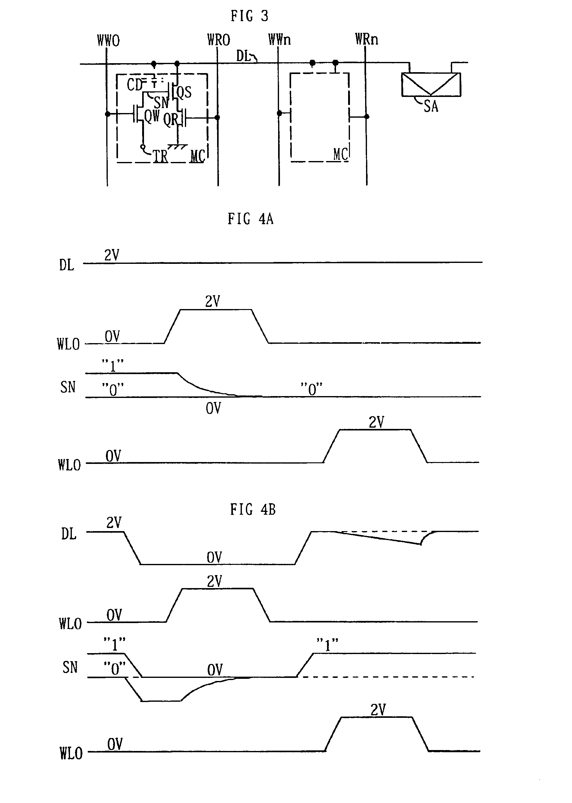
[0095]In this embodiment, two dummy cells DC are preferably included in each column with the output of one dummy cell connected to one of a pair of data lines D0, D1, and the output of the other connected to the other in a pair of data lines. As in the second embodiment, the dummy cell DC is constructed to generate a signal that is roughly midway between the two signals generated by a normal memory cell. During a read operation, data is presented to only one data line of a pair D0, D1 by the accessed memory cell. The activation of the dummy word line DR corresponding to the dummy cell DC connected to the other data line of the pair will present the reference signal. This pair is presented to the differential sense amplifier SA, which amplifies the difference on the data lines to a full voltage swing as described previously. The dummy cell solution allows an adequate reference to be generated for each data line pair D0, D1, resulting in a faster read operation.

[0096]The write operati...
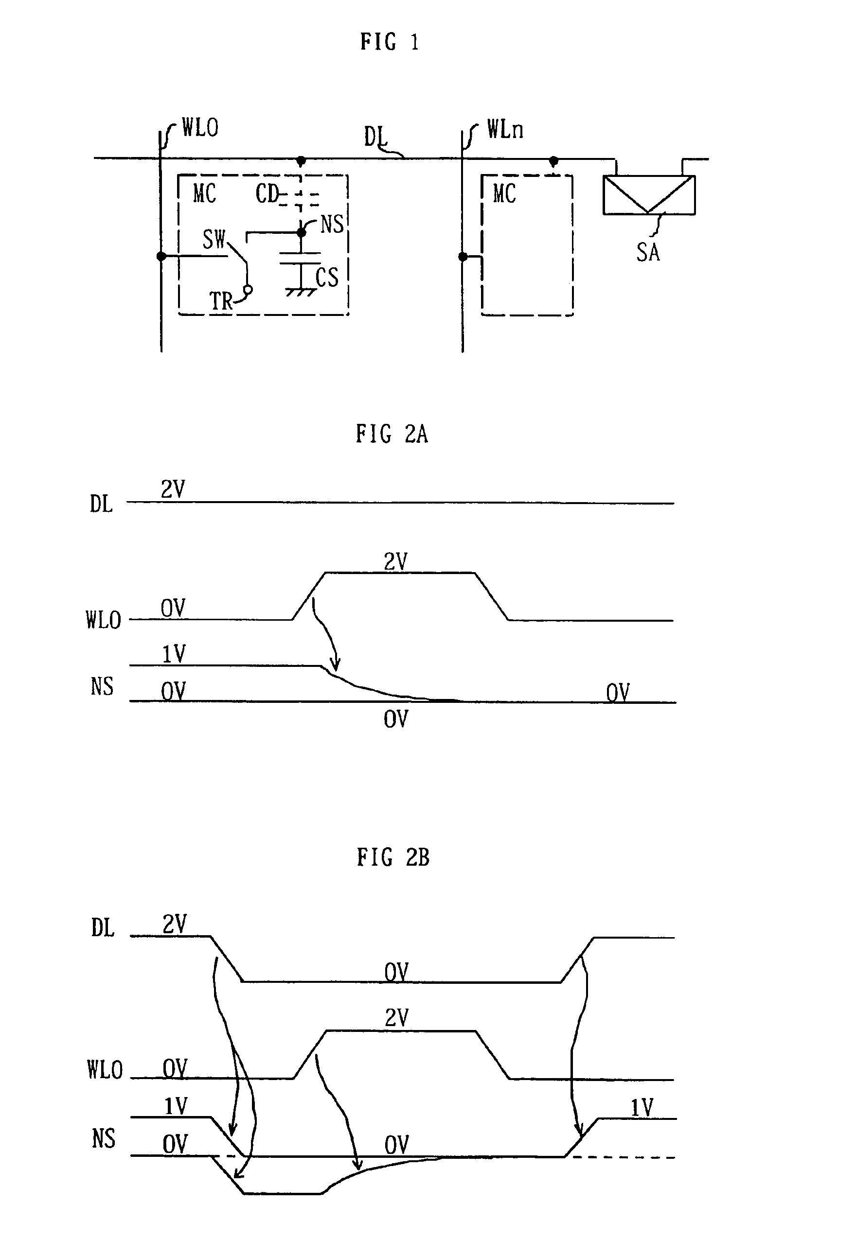
first embodiment

[0099]The memory described in this embodiment preferably incorporates a refresh method divided into two separate cycles. In the first cycle, the data for the row of cells being refreshed is read into a storage register LE. This follows a similar operation as a standard read cycle in the first embodiment except that after the voltage is fully developed in the sense amplifier SA and the output data line DOUT, the data is stored in a register LE through the input TD by the activation of the data store signal at the node TC. In a subsequent cycle, the refresh operation continues with the voltage on the storage node NS being fully restored. During this cycle, the voltage stored in the storage register is presented to the input data DIN and passed to the read data line D0 directly through the activation of the N-channel and P-channel pass transistor pair Q5, Q7. After this data is set on the read data line, the write word line for the row under refresh is activated and deactivated, and th...
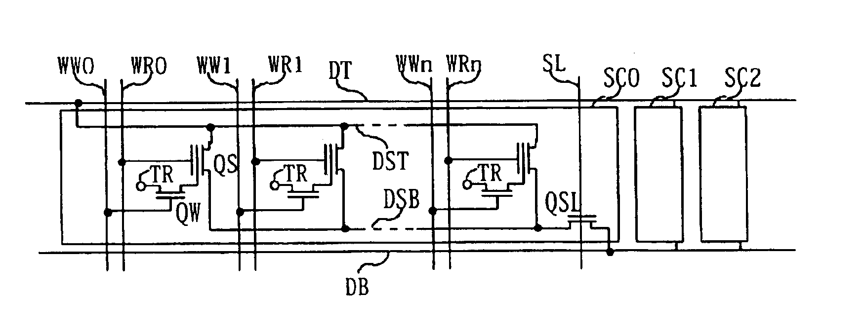
third embodiment

[0109]A write operation begins with a similar read data line DR0 and source data line DL0 activation method as described in the third exemplary embodiment. After the read data line DR0 and source data line DL0 are set at appropriate voltages, the word line WL0 is raised to a high voltage that activates the write transistor QW and equalizes the storage node NS with the fixed voltage reference TR. Following word line W10 deactivation, the read and source data lines are returned to the standby state, storing a voltage value on the storage node NS. As in the third embodiment, the stored voltage in the high state is Vref+Vr*Cr / Ctot and the voltage of the low state is Vref−Vs*Cs / Ctot. The values are designed such that the low voltage state does not activate the storage transistor QS.

[0110]A read operation is started when the read data line DR0 is floated and the word line WL0 voltage is lowered. The change in voltage induced on the storage node is −Vw*Cw / Ctot. These values are designed su...


PUM


Abstract

A high integration dynamic random access memory is provided by this invention. Furthermore, a write method is provided such that the cell size of two-and three-transistor gain cell memories is reduced. A dynamic memory incorporating a thin-channel transistor as the write element such that long data storage retention is achieved in the memory devices of this invention. A dynamic memory cell having low operating power and high density is also realized by this invention.

Description

[0001]This application is a Continuation of nonprovisional U.S. application Ser. No. 10 / 167,754 filed Jun. 11, 2002 now U.S. Pat. No. 6,787,835. Priority is claimed based on U.S. application Ser. No. 10 / 167,754 filed Jun. 11, 2002.BACKGROUND OF THE INVENTION[0002]1. Field of the Invention[0003]The present invention relates to a semiconductor memory, especially a dynamic random access memory (DRAM), and more particularly, the present invention relates to a series of cell structures, arrangements, and activation schemes for high density, low power semiconductor memories.[0004]2. Description of the Background[0005]A conventional DRAM memory cell, consisting of one transistor and one capacitor (referred to as a 1T-1C configuration), is commonly used as a semiconductor memory when high bit density is required. This technology has several drawbacks and faces serious complications as device dimensions are scaled smaller. Most notably, since the DRAM cell has no internal gain, a high capaci...

Claims


Application Information

Patent Timeline
Patent Type & Authority Patents(United States)
IPC IPC(8): G11C11/405G11C11/4076G11C11/403G11C11/406G11C11/407H01L27/108H01L27/12H01L27/105G11C11/00G11C11/401H01L21/8242
CPCG11C11/405G11C11/406G11C11/4076H01L27/105H01L27/108H01L27/1203G11C2207/2281G11C2207/229H01L27/0207H10B12/00G11C11/401
Inventor ATWOOD, BRYANYANO, KAZUOISHII, TOMOYUKIOSABE, TAROYANAGISAWA, KAZUMASASAKATA, TAKESHI
Owner HITACHI LTD
Why Eureka
Try Eureka