Flue gas desulfurization process and apparatus for removing nitrogen oxides

a technology of gas desulfurization and nitrogen oxides, which is applied in the direction of separation processes, lithium compounds, synthetic resin layered products, etc., can solve the problems of large quantities of wastes or gypsum, only nominal commercial value, and environmental hazards

Inactive Publication Date: 2005-10-25
BANK OF MONTREAL AS ADMINISTATIVE AGENT +1
View PDF0 Cites 5 Cited by
  • Summary
  • Abstract
  • Description
  • Claims
  • Application Information

AI Technical Summary

Benefits of technology

[0009]The process of this invention generally entails contacting a flue gas with a scrubbing medium, preferably an ammonium sulfate-containing scrubbing solution, to absorb acidic gases from the flue gas and produce an acidic gas-containing solution and an intermediate flue gas. According to the invention, after contact with the scrubbing medium, the intermediate flue gas is cooled to cause nitric oxide to be oxidized to form nitrogen dioxide, which is then absorbed from the intermediate flue gas to produce a NO2-containing solution and a more fully scrubbed flue gas. The nitrogen dioxide in the NO2-containing solution is then reacted with an aqueous ammonia solution to form ammonium nitrate (NH4NO3) as the valuable byproduct of the process. A flue gas scrubbing apparatus suitable for use with this invention comprises means for contacting the flue gas with the scrubbing medium to remove acidic gases and produce the intermediate flu...

Problems solved by technology

Acidic gases, including sulfur dioxide (SO2), hydrogen chloride (HCl) and hydrogen fluoride (HF), are known to be hazardous to the environment, and as a result their emission into the atmosphere is closely regulated by clean air statutes.
While scrubbers utilizing calcium-based slurries generally perform satisfactorily, their operation results in the production of large quantities of wastes or gypsum, the latter having only nominal commercial value.
The presence of NOx ...

Method used


Image

  • Flue gas desulfurization process and apparatus for removing nitrogen oxides
  • Flue gas desulfurization process and apparatus for removing nitrogen oxides

Examples


Embodiment Construction

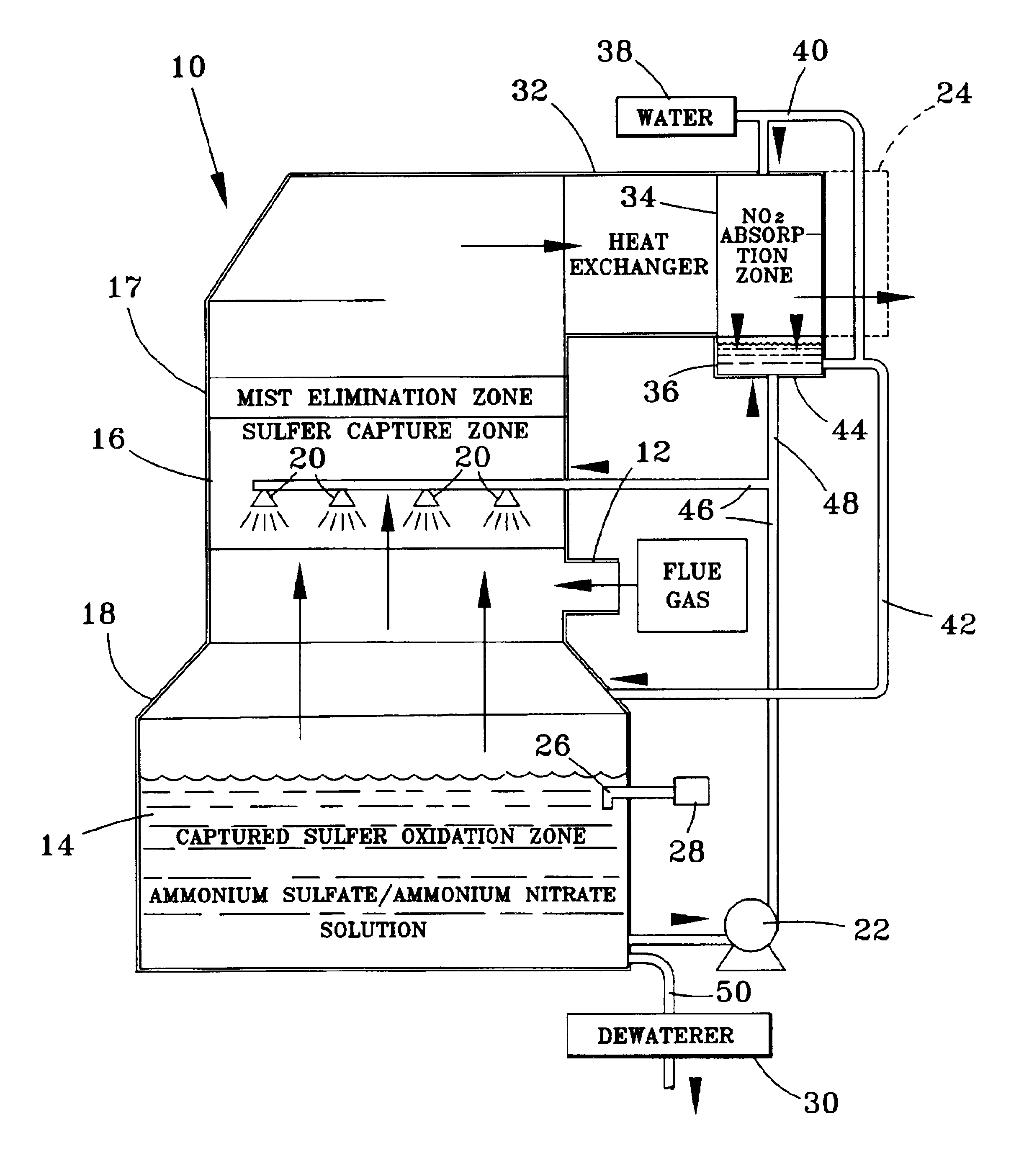
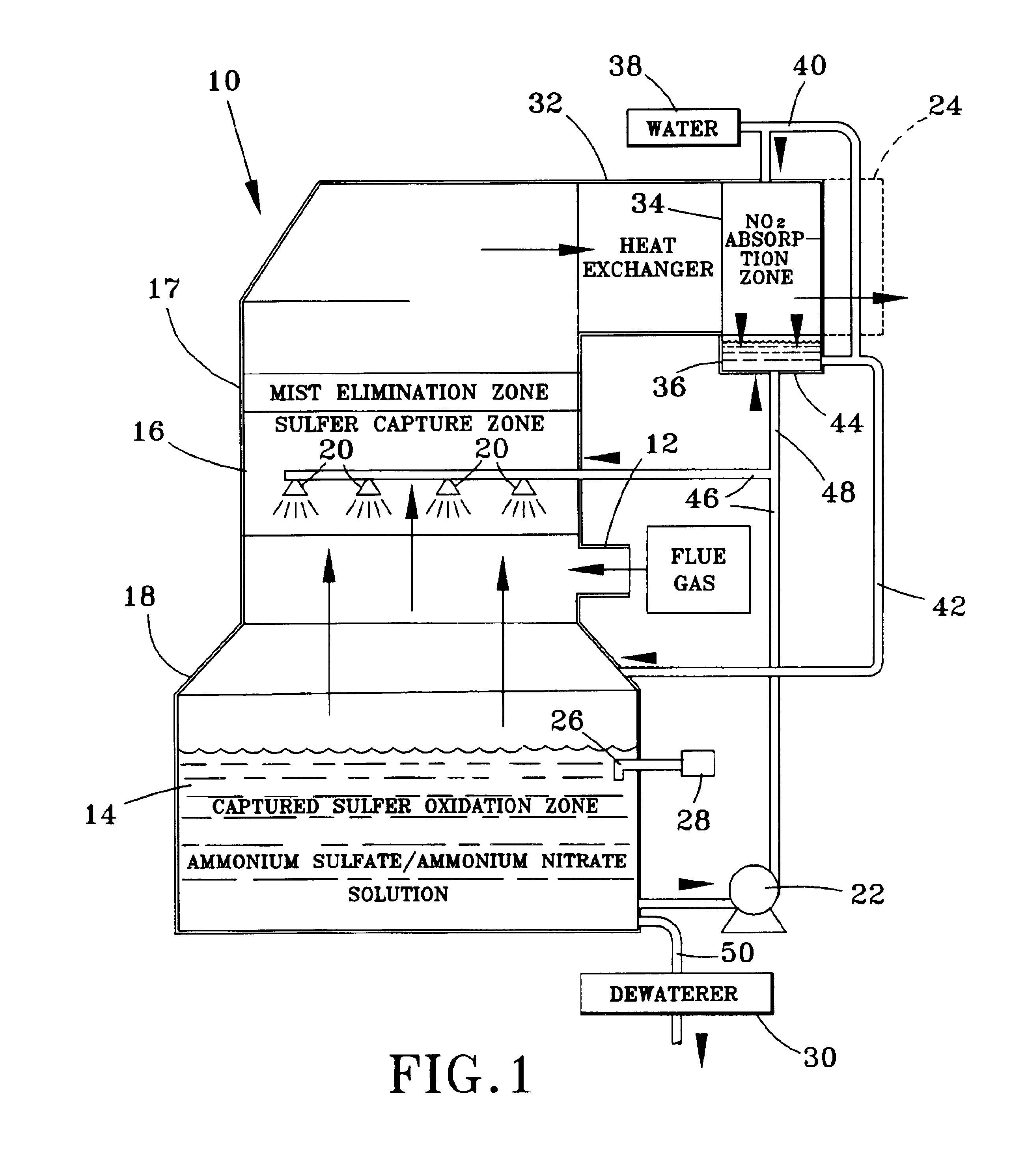
[0013]FIG. 1 schematically illustrates a flue gas scrubbing apparatus 10 that has been modified in accordance with the teachings of this invention. The scrubber 10 is generally of the type that scrubs flue gases produced by the burning of fossil fuels or another process that results in the flue gas containing acidic gases, such as sulfur dioxide, hydrogen chloride and / or hydrogen fluoride, as well as particulate matter and, of interest to the present invention, nitrogen oxides (NOx).

[0014]The conventional components of the scrubber 10 include a contact region 16 in which an alkaline contact medium, referred to as a scrubbing slurry or solution 14, is brought into contact with a flue gas that enters the scrubber 10 through an inlet duct 12. The solution 14 is shown as being delivered with a pump 22 through a pipe 46 to the contact region 16, where the solution 14 is dispersed with spray nozzles 20 or another suitable delivery device. After being scrubbed by the solution 14, the flu...


PUM

PropertyMeasurementUnit
Temperatureaaaaaaaaaa

Abstract

An apparatus and process for removing acidic gases and NOx from flue gases produced by utility and industrial plants. The process and apparatus convert NOx, and particularly nitric oxide, to nitrogen dioxide, which is then reacted to form a valuable byproduct. The process generally entails contacting a flue gas with a scrubbing medium to absorb acidic gases from flue gas and produce an intermediate flue gas. The intermediate flue gas is then cooled to cause nitric oxide present therein to be oxidized to form nitrogen dioxide, which is then absorbed from the flue gases to produce a nitrogen dioxide-containing solution and a scrubbed flue gas. The nitrogen dioxide in the nitrogen dioxide-containing solution is then reacted with ammonium hydroxide to form ammonium nitrate as a valuable byproduct.

Description

[0001]This application is a division of U.S. application Ser. No. 10 / 064,055 filed on Jun. 5, 2002, now U.S. Pat. No. 6,759,022.BACKGROUND OF INVENTION[0002]1. Field of the Invention[0003]This invention generally relates to gas-liquid contactors used in the removal of acidic gases, such as from utility and industrial flue gases. More particularly, this invention is directed to a wet flue gas desulfurization (FGD) process and apparatus that remove nitrogen oxides (NOx) from a flue gas following the removal of acidic gases such as sulfur dioxide.[0004]2. Description of the Related Art[0005]Acidic gases, including sulfur dioxide (SO2), hydrogen chloride (HCl) and hydrogen fluoride (HF), are known to be hazardous to the environment, and as a result their emission into the atmosphere is closely regulated by clean air statutes. For the removal of acidic gases from flue gases produced by utility and industrial plants, gas-liquid contactors and absorbers, or scrubbers, are widely employed. ...

Claims


Application Information

Patent Timeline
IPC IPC(8): B01D53/14B01D53/73B01D53/56C01C1/00C01C1/242C01C1/18
CPCB01D53/1456B01D53/56B01D53/73C01C1/185C01C1/242
Inventor HAMMER, MICHAEL T.MENGEL, MICHAEL L.
Owner BANK OF MONTREAL AS ADMINISTATIVE AGENT
Why Eureka
Try Eureka