Balloon catheter

a balloon catheter and balloon technology, applied in balloon catheters, other medical devices, surgery, etc., can solve the problems of large decline in controllability, significant increase in proportion, and large decrease in controllability

Inactive Publication Date: 2005-11-01
KANEKA CORP
View PDF24 Cites 41 Cited by
  • Summary
  • Abstract
  • Description
  • Claims
  • Application Information

AI Technical Summary

Benefits of technology

[0043]Thus, with the leading end of the balloon catheter inserted into the interior of the protective pipe, and protectively covered thereby, the flushing fluid supply device is connected to the coupling adapter, whereupon flushing can be done, supplying the flushing fluid to the guide wire lumen of the balloon catheter through that flushing fluid supply device. During this flushing operation, the leading end of the balloon catheter is protectively covered inside the protective pipe, wherefore that leading end is protected from being bent, deformed into a trumpet shape, or otherwise damaged.
[0044]When a hypodermic syringe is used as the flushing fluid supply device, moreover, if a comparatively small hypodermic syringe is used, a coupling port should be provided in the coupling adapter to which the barrel end of the hypodermic syringe is fitted so that it can be freely attached and detached. If a comparatively large hypodermic syringe is used, a Luer taper lock fitting coupling for connecting the flushing fluid supply device should be provided in the coupling adapter. The coupling adapter may also be provided with a coupling port to which a hypodermic needle protecting member is fitted so that it can be freely attached and detached.

Problems solved by technology

The reason is that, when the catheter is deployed in a curved segment, if there is discontinuity in the flexibility, discontinuity will also develop in the way the catheter bends, the guide wire resistance in that portion will become significantly larger, and that will cause controllability to decline.
When this tip portion is hard, the difference in flexibility with the guide wire emerging from the tip becomes great, the guide wire readily bends at that place, and, as a result, a large decline in controllability ensues.
If at such time the tip portion is hard, similarly as the calcified lesion, a problem arises in that the balloon catheter catches on the metal stent and will not pass.
As a low-friction material, high-density polyethylene is outstanding, but it is poor in terms of fusability and bondability with the other main materials, and cannot be fused with any other than a polyolefin material, wherefore only bonding means have been available with other materials.
With balloons made of polyolefin materials, it is impossible of make the skin thin in the portion that becomes fusion material due to the need for cross-linking in the material, wherefore, as a result, it has not been possible to make the tip portion flexible even by fusion.
High-density polyethylenes that exhibit outstanding low friction properties are inferior in flexibility, while the low-density polyethylenes that are comparatively flexible are almost never used because the friction and sliding properties decline precipitously as the flexibility thereof increases.
And when a polyethylene single-layer tubular member is used for the guide wire passing tubular member, it has been very difficult to impart adequate flexibility to the tip portion.
However, it has not been possible thereby to impart sufficient flexibility to the tip portion because polyamides generally have a higher elastic modulus than polyethylenes.
There are also commercially available balloon catheters that are configured with a polyamide elastomer balloon and a guide wire passing tubular member made of a polyamide elastomer having higher hardness and a higher melting point than the balloon, wherein the balloon and the tubular member are fused together, but the tip portions thereof have not been adequately flexible because a harder material is deployed in the guide wire passing tubular member than in the balloon.
Taking a PTCA balloon catheter as an example, when dilating a hard stricture that has calcified or where a stent has been left in place, high pressure-withstanding strength becomes necessary, but materials exhibiting high pressure-withstanding strength tend generally to lack flexibility.
If balloon flexibility is not maintained, recrossing performance declines, particularly when reusing the balloon.
That is, the limitation on the elongation in the radial dimension relative to the inflation pressure in the balloon (compliance characteristic) is very critical.
However, although the ideal balloon exhibits abundant flexibility, high pressure-withstanding strength, and suitable elongation (compliance characteristic), these characteristics are mutually contradictory from the perspective of the physical properties of the balloon material.
However, in these advanced technologies, balloon flexibility and strength vary greatly according to the ratio in which the two components are mixed, and there has been a problem in that optimizing the mixture ratio is very difficult.
In the case of the layered balloon described in TOKUHYO H9-506008 (published), moreover, the extrusion molding process for fabricating the tubular parisons that are the raw materials for the balloons is demandingly complex, is problematic in terms of higher production costs, and also involves the possibility that inter-layer peeling will occur in the layered balloons that are fabricated.
Thus there is a problem in that it is very difficult to perform repeat dilatation treatments using the same balloon.
If that balloon is then advanced forcibly, there is a considerable danger that the stent will be pushed to the distal side of the blood vessel, moving the stent out of position.
With the balloon described in the publication cited above, however, the vertical groove(s) remain(s) when the balloon is inflated unless the internal pressure applied is at least as high as a certain level, and there is a problem in that the outer cross-sectional shape will not become truly circular.
If the outer cross-sectional shape will not become truly circular, a stricture cannot be dilated evenly about its entire circumference, and the danger of the stricture reforming within a short time is high.
When bending or other damage has been inflicted on the balloon portion, the balloon can easily scratch the vascular inner walls when it is passed through a vascular lumen.
Thus it becomes very difficult to guide the balloon accurately to the lesion site.
Also, when a balloon that has sustained damage is inflated, there is a great danger of the balloon bursting or the pressurized fluid leaking, and there are cases where this has led to a serious medical accident.
With a monorail type balloon catheter, however, the situation is unlike that with an over-the-wire type.
Therefore, when a hypodermic needle is inserted into the guide wire lumen from the leading end opening, not only is that operation very intricate, but trouble readily ensues, such as the leading end becoming bent or deformed into a trumpet shape, or otherwise damaged.
When that happens, it becomes extremely difficult to guide the balloon all the way to the lesion site during the procedure.

Method used


Image

  • Balloon catheter
  • Balloon catheter
  • Balloon catheter

Examples


embodiment 1

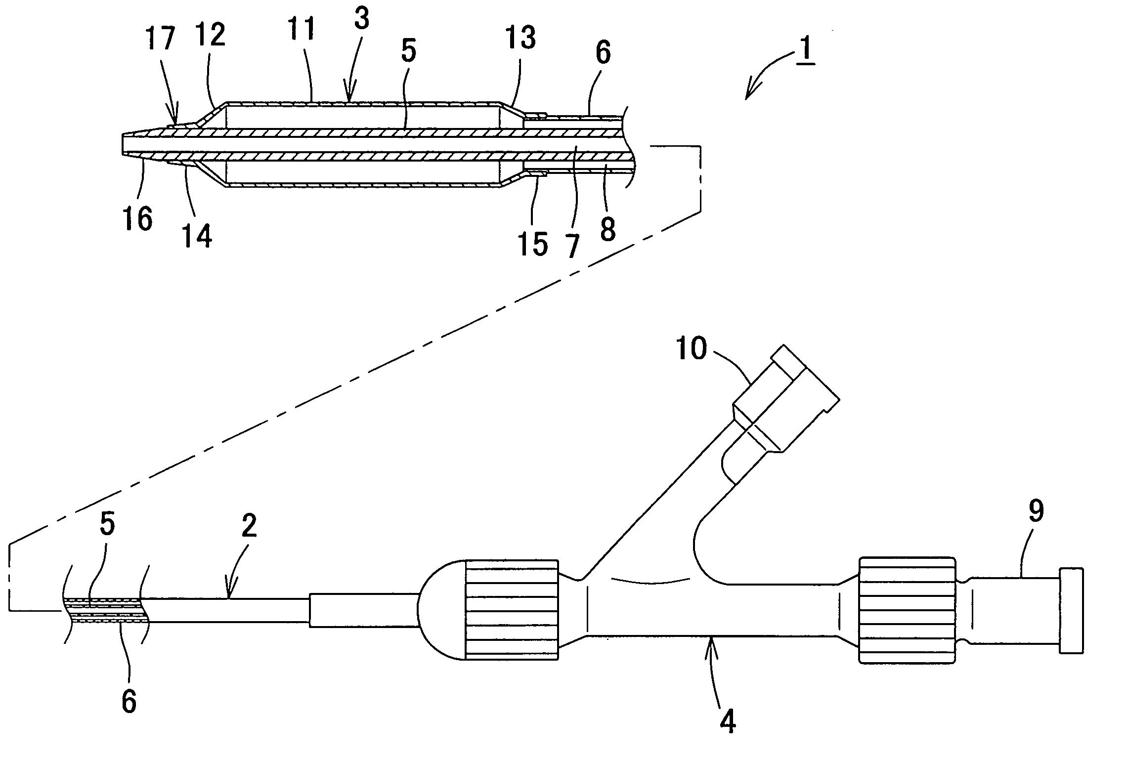
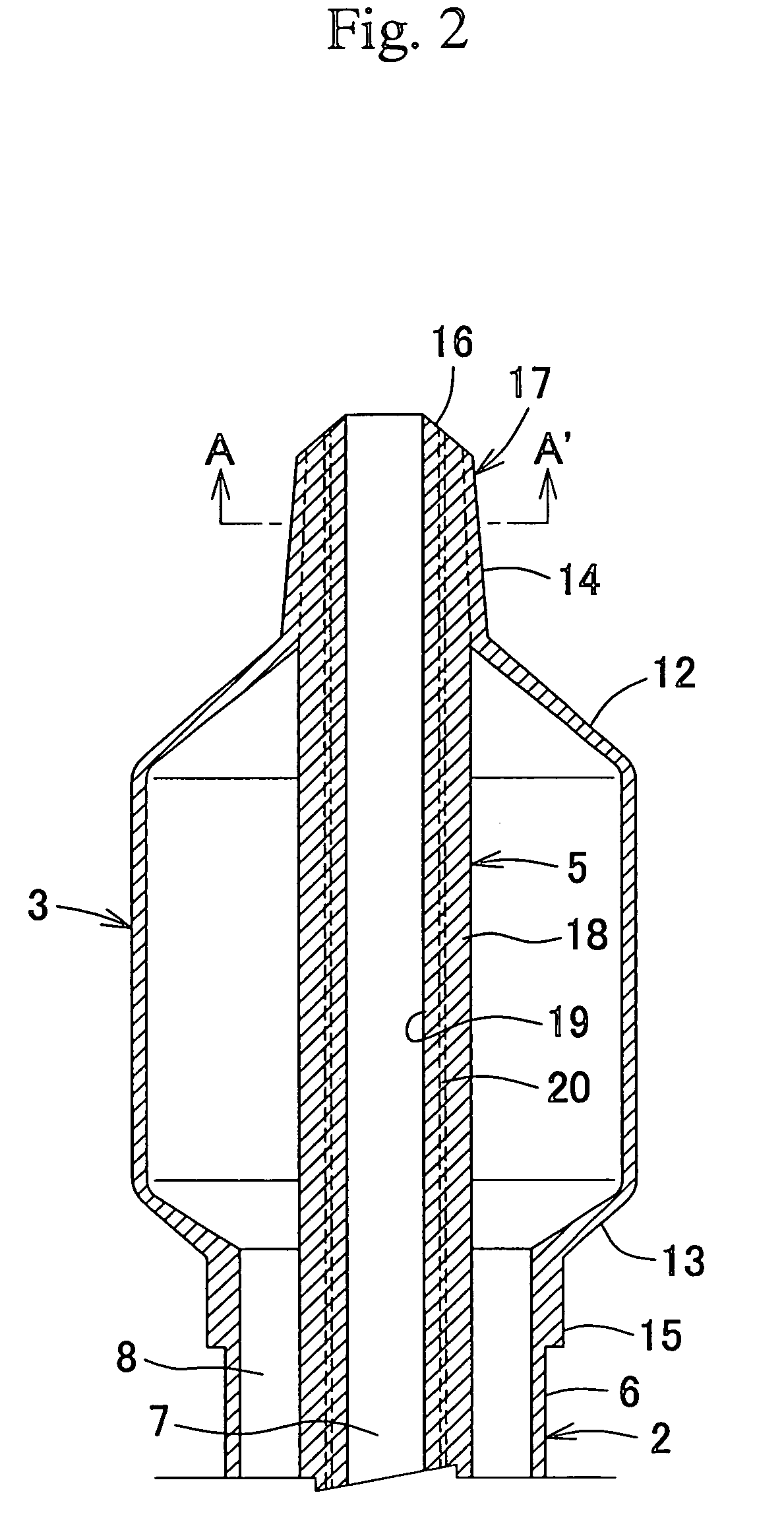
[0089]A rapid exchange type balloon catheter for use in coronary arteries having a catheter distal portion as diagrammed in FIG. 2 was fabricated by passing a first tubular member for passing a guide wire, having the layer forming the outermost surface configured from a polyester elastomer having a Shore hardness of 60D, flexural modulus of 274 Mpa, melting point of 216° C., and soft segment ratio of 22% and the innermost surface configured from a high-density polyethylene through the interior of a balloon having a nominal inflated diameter of 3.0 mm formed from a polyester elastomer having a Shore hardness of 72D, flexural modulus of 568 MPa, melting point of 218° C., and soft segment ratio of 13%, and fusing the outer surface of that first tubular member concentrically at the distal-side leading end of the balloon. In this Embodiment 1, furthermore, a second tubular member configuring the catheter outer surface connected to the proximal side of the balloon was configured of a poly...

embodiment 2

[0090]A rapid exchange type balloon catheter for use in coronary arteries having a catheter distal portion as diagrammed in FIG. 2 was fabricated by passing a first tubular member for passing a guide wire, having the layer forming the outermost surface configured from a polyamide elastomer having a Shore hardness of 55D, flexural modulus of 196 Mpa, melting point of 168° C., and soft segment ratio of 35% and the innermost surface configured from a high-density polyethylene through the interior of a balloon having a nominal inflated diameter of 3.0 mm formed from a polyamide elastomer having a Shore hardness of 70D, flexural modulus of 430 MPa, melting point of 172° C., and soft segment ratio of 14%, and fusing the outer surface of that first tubular member concentrically at the distal-side leading end of the balloon. In this Embodiment 2, furthermore, a second tubular member configuring the catheter outer surface connected to the proximal side of the balloon was configured of a poly...

embodiment 3

[0091]A rapid exchange type balloon catheter for use in coronary arteries having a catheter distal portion as diagrammed in FIG. 7 was fabricated by passing a first tubular member for passing a guide wire, having the layer forming the outermost surface of the portion fused with the balloon configured from a polyamide elastomer having a Shore hardness of 40D, flexural modulus of 93 Mpa, melting point of 168° C., and soft segment ratio of 47% and the innermost surface of the portion fused with the main body and balloon configured from a high-density polyethylene through the interior of a balloon having a nominal inflated diameter of 3.0 mm formed from a polyamide elastomer having a Shore hardness of 70D, flexural modulus of 430 MPa, melting point of 172° C., and soft segment ratio of 14%, and fusing the outer surface of that first tubular member concentrically at the distal-side leading end of the balloon. The symbol 26 in FIG. 7 here indicates an opening for leading in the guide wire...


PUM

PropertyMeasurementUnit
angle of inclinationaaaaaaaaaa
lengthaaaaaaaaaa
outer diameteraaaaaaaaaa

Abstract

The present invention is a balloon catheter used primarily in treatment and surgery for the purpose of dilating lesion sites such as strictures or blockages in passages in the human body. The balloon catheter of the present invention has a structure wherein a guide wire passing tubular member is deployed passing through the interior of the expansion body, and the outer surface of the tubular member and the expansion body are concentrically fused near the distal end of the catheter. This is a balloon catheter that is characterized by the fact that the Shore hardness of the material configuring the outermost surface of the tubular member is smaller than the Shore hardness of the material configuring the expansion body. It is therefore possible to flexibly adjust the tip portion formed by securing the expansion body and the guide wire passing tubular member.

Description

BACKGROUND OF THE INVENTION[0001]1. Field of the Invention[0002]This invention relates to a balloon catheter used primarily in medical treatment and surgery for the purpose of dilating lesion sites such as strictures or blockages in passages in the body, and more particularly to a balloon catheter used in percutaneous translumin angioplasty (PTA) and percutaneous translumin coronary angioplasty (PTCA), etc., for forming peripheral blood vessels, coronary arteries, and valves.[0003]2. Description of the Related Art[0004]Balloon catheters are used primarily in internal passage anaplasty performed on internal passages that have become constricted or blocked. In general, a balloon catheter is structured such that it has a balloon connected to an expansion lumen for supplying a pressurized fluid in the leading end portion of a tubular catheter shaft having a plurality of lumens in the interior thereof, and such that it has ports that connect to the lumens in the base end part. In its nor...

Claims


Application Information

Patent Timeline
Patent Type & Authority Patents(United States)
IPC IPC(8): A61M25/00A61M29/02A61M25/10A61F2/958
CPCA61M25/1027A61M25/104A61M25/0045A61M25/0068A61M25/1002A61M25/1038A61M2025/0004A61M2025/0183A61M2025/1056A61M2025/1093A61M25/10
Inventor FUKAYA, KOHEINISHIDE, TAKUJINAKANO, RYOJIMAEDA, HIROMIMIKI, SHOGO
Owner KANEKA CORP
Why Eureka
Try Eureka