Electronic shut off systems

a technology of electronic shut off and system, applied in the direction of propellers, vessel construction, marine propulsion, etc., can solve the problems of inefficiency, inefficiency, and inability to control the speed of the rotating motor shaft or gear, and achieve the effect of quick stopping a propeller

Inactive Publication Date: 2005-11-29
MOTSENBOCKER MARVIN A
View PDF18 Cites 29 Cited by
  • Summary
  • Abstract
  • Description
  • Claims
  • Application Information

AI Technical Summary

Benefits of technology

[0013]Embodiments provide systems that can, for example, quickly stop a propeller or other device before the device can significantly damage an object that appears nearby. In embodiments an electronic sensor detects a solid object that en

Problems solved by technology

Most energy from a transportation energy source dissipates as heat because of inefficiencies during chemical energy conversion into mechanical work.
A major inefficiency is the mismatch between a faster rotating motor shaft or gear and a slower rotating device that receives such energy such as a wheel of a car or propeller of a boat.
Unfortunately, each system has its own inefficiencies and problems.
For example, in the case of powered watercraft that employ a fixed gear ratio, energy is lost from friction in the reducing gear and also in the propeller of such drive systems because the small propellers used represent a compromise and rotate at a much higher than ideal rate to push water efficiently.
Inexpensive gears and transmissions generally are not available for such high ratio speed changes.
Another practical limitation is that while reduction gears with ratios as great as 6 or 7 to 1 are available for larger marine engines of, say over 250 hp (185 kw). standard reduction gears .
. . are seldom available with ratios larger than 3 to 1 . . . . ″ According to this reasoning, a highly efficient and simple gear reduction of greater ratios approaching 10 or even 20 fold would give great benefits for many watercraft but is not readily available for regular watercraft.
A related problem is the need to rapidly stop a propeller, conveyor or other equipment upon detection of an unsafe condition.
For example, a spinning propeller poses great hazards to swimmers and other waterlife.
A rapid propeller stop system, is highly desirable but generally not considered because of the extreme difficulty in rapidly stopping a propeller.
A limitation in this regard is that most propeller shafts are permanently fixed to a motor, either directly or indirectly through reduction gearing and rapid stoppage would overstress the drive system, due to the inertia of moving parts.
Unfortunately, such system generally is not available.
Other mammals such as manatees are severely injured and disfigured and this problem threatens the tourism industry in areas such as Homosassa Springs State Park in Florida.
The boating industry has struggled with this problem without much success for some time.
The often proposed solution of using a mechanical propeller guard to physically block contact, while logical at first glance actually is very impractical, despite a number of attempts to implement this idea as described in U.S. Pat. Nos. 3,889,624; 4,411,631; 44,826,461; 4,078,516; 5,238,432; 4,957,4459;

Method used


Image

  • Electronic shut off systems
  • Electronic shut off systems
  • Electronic shut off systems

Examples


example 1

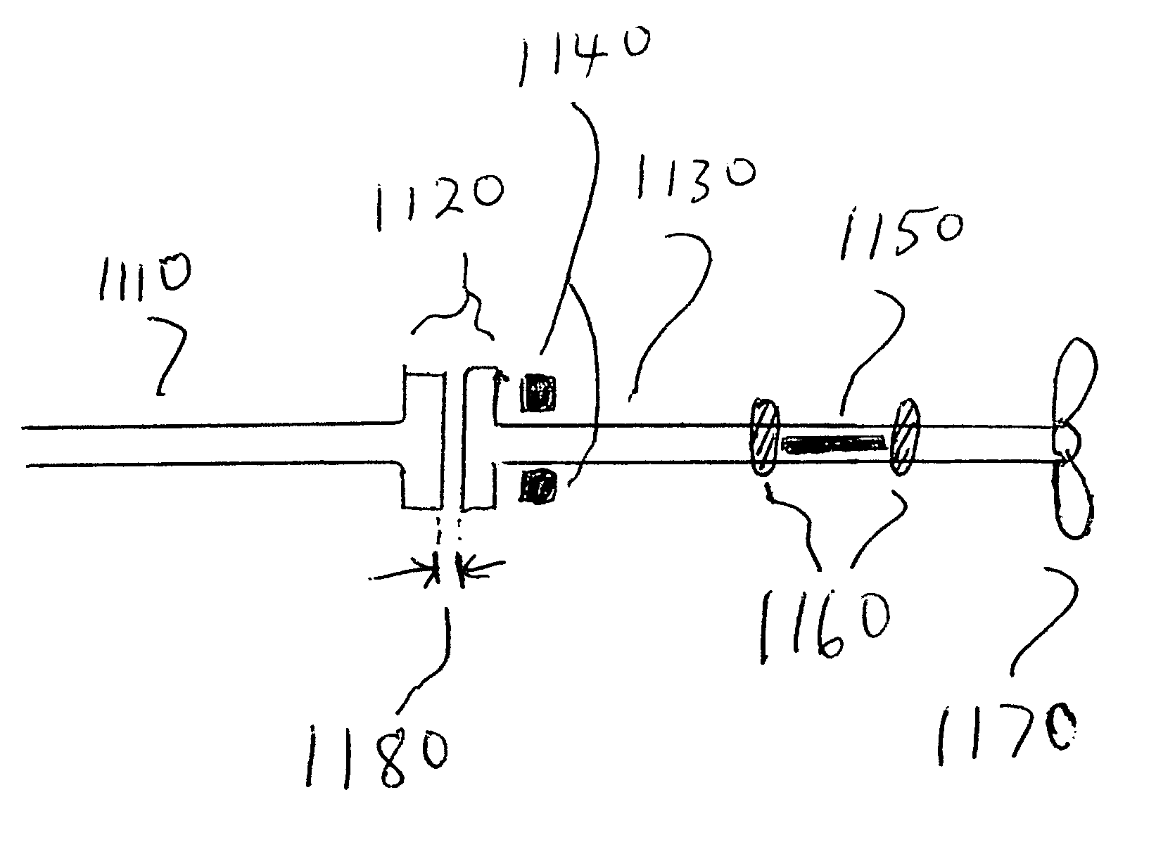
[0178]Acoustic sensor 1220 is mounted on the port side of boat fuselage 1200 as shown in FIG. 12a. The sensor comprises a flat quartz crystal and a drive / monitoring circuit (located inside the boat) and is adjusted to provide a signal when a submerged solid object presenting more than 1 square inch cross sectional area is placed 15 inches directly in front. Another piezoelectric from a second sensor is mounted on the opposite starboard side of fuselage 1200. The faces (plane of the vibrating piezoelectric crystal) of the sensors are pointed forwards away from the propeller at a 10 degree angle away (toward the starboard and port sides respectively) from the central axis of the boat such that each sensor monitors the water on each respective side of fuselage in front of the propeller.

[0179]The signals from the two sensors trigger an activator. The activator may brake an internal combustion engine or may control one or more electromagnets such as the power to the armature of a permane...

example 2

[0182]In this example galvinometric measurements are made using electrodes distributed on two fin surfaces in a pattern such as shown in FIG. 13a and FIG. 13c. The measurements are input into a comparator that monitors and adjusts for long term (more than 5 seconds) changes in conductivity. When a solid object enters the volume between the upper and lower electrodes, galvinometric measurements indicate a short term change in conductivity and output a signal to a control circuit, stopping the propeller. In further embodiments conductivity between pairs of facing electrodes is used to detect an approaching body, which perturbs conductivity between the left most electrodes before doing so to pairs of electrodes to the right. A multihull watercraft may employ galvanometic sensing by the use of sensors on different hulls in contact with the water in front of a propeller.

example 3

[0183]In this example, boat hull 1550 of FIG. 15b (bottom view) has an attached propeller 1560 and a outside-rear facing piezoelectric sensor 1556. A second sensor 1555 that also faces outside (away from the boat) and towards the rear is mounted on the opposite side from sensor 1560. Both sensors (including their signal analysis circuitry) monitor for intrusion of a solid body and are adjusted to ignore signals from the propeller. In one case, one sensor acts as a transmitter to the other. For example, sensor 1555 emits a sonic signal while sensor 1560 monitors for a reflection of that signal by a solid object. In an embodiment, the two sensors alternate transmission to the other, and obtain more information about the size and / or movement of a detected solid object that way.

[0184]A number of algorithms may be used to extract more information and to improve signal to noise with respect to the propeller. In one such algorithm, a signal obtained from sensor 1555 upon transmission by se...


PUM


Abstract

Rapid shaft stop devices and transmissions are described that utilize permanent magnets for coupling and/or braking and are useful for electronic propeller guards and other equipment. In an embodiment, one or more capacitive discharge pulses are used to rapidly stop a shaft. A magnetic transmission is provided having axially oriented magnets on each side of an air space junction that transmit torque across the junction with a torque/speed profile that particularly suits boat propellers. The junction may include a bearing and allows slippage when the propeller resistance exceeds a given value. This slippage acts as a variable gear reduction. One or more electromagnets may be energized and thereby add to or subtract from one or more magnetic fields and provide electronic control of torque and of gear reduction ratio for devices such as watercraft drive systems.

Description

REFERENCE TO RELATED APPLICATIONS[0001]This application is a continuation in part of U.S. Ser. No. 10 / 187,830 filed Jul. 3, 2002, now U.S. Pat. No. 6,676,460 and a continuation of U.S. Ser. No. 10 / 724,240 filed Dec. 1, 2003, which in turn enjoy priority from U.S. provisional application Nos. 60 / 323,723 filed Sep. 21, 2001, 60 / 302,647 filed Jul. 5, 2001, 60 / 349,375 filed Dec. 22, 2001, 60 / 431,200 filed Dec. 6, 2002, and 60 / 433,591 filed Dec. 16, 2002, and also enjoys priority from U.S. Nos. 60 / 445,249 filed Feb. 6, 2003, 60 / 474,957 filed Jun. 3, 2003 and is a CIP of Ser. No. 10 / 620,618 filed Jul. 17, 2003 now abandoned the contents of which are incorporated by reference in their entireties.FIELD OF THE INVENTION[0002]The invention relates to machinery and rapid stopping of motor driven machinery such as electric saws, meat cutters, robots, and motor driven propellers in response to sensed conditions.BACKGROUND OF THE INVENTION[0003]Energy efficiency is a major concern that affects ne...

Claims


Application Information

Patent Timeline
IPC IPC(8): B63H5/16B63H21/22H03K17/945
CPCB63H5/165B63H21/22B63H23/30H03K17/945
Inventor MOTSENBOCKER, MARVIN A.
Owner MOTSENBOCKER MARVIN A
Why Eureka
Try Eureka