
Multilayer structure including an active electrochemical material and ionic polymer in a electrochemical cell

a multi-layer structure and electrochemical cell technology, applied in the direction of non-aqueous electrolyte cells, cell components, sustainable manufacturing/processing, etc., can solve the problems of difficult to process volatile liquids or thermally unstable materials, difficult to process volatile liquids, and high drying rates, so as to minimize the exposure of components

Inactive Publication Date: 2006-01-17
EI DU PONT DE NEMOURS & CO
View PDF28 Cites 54 Cited by
  • Summary
  • Abstract
  • Description
  • Claims
  • Application Information

AI Technical Summary

Benefits of technology

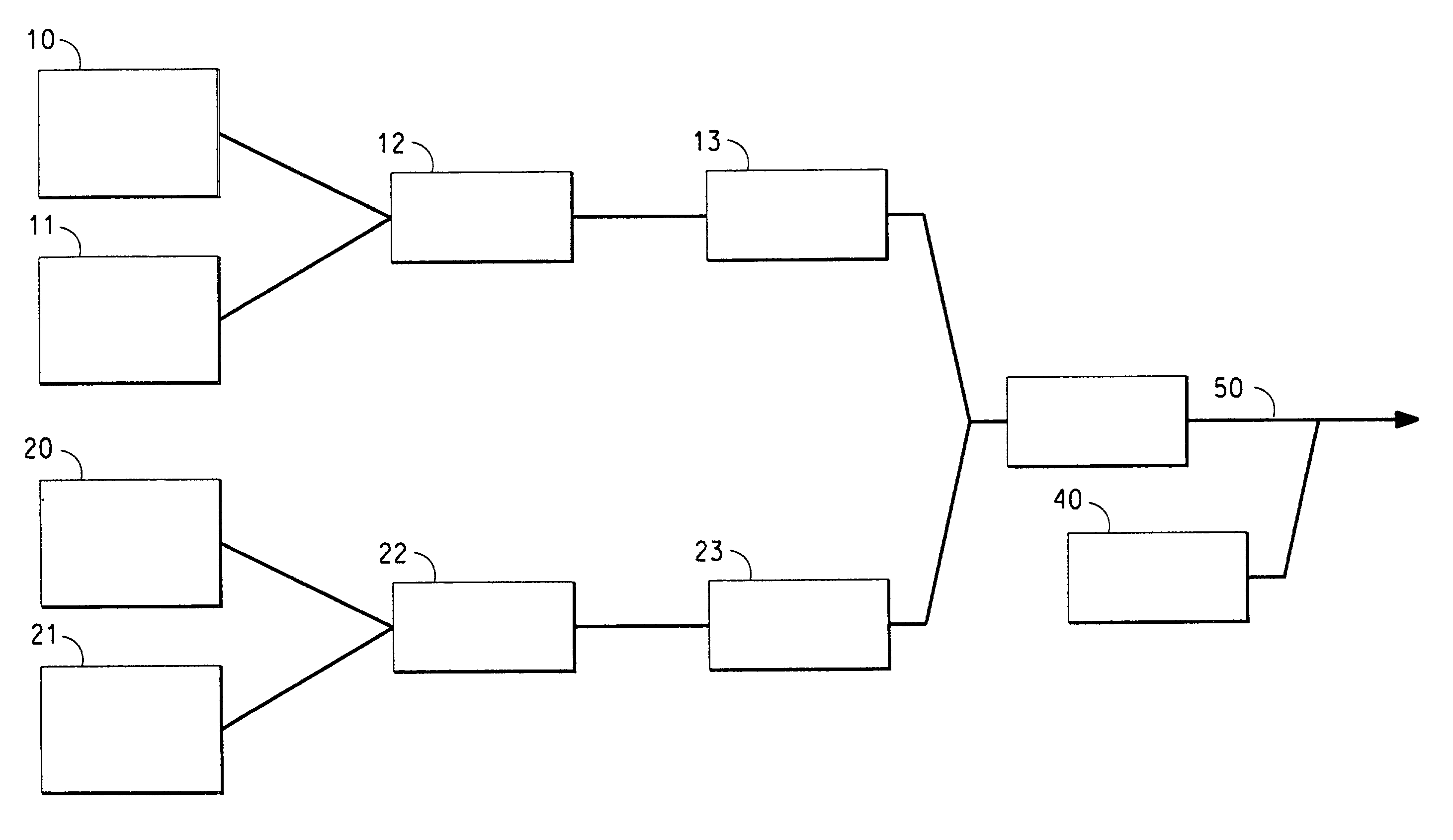
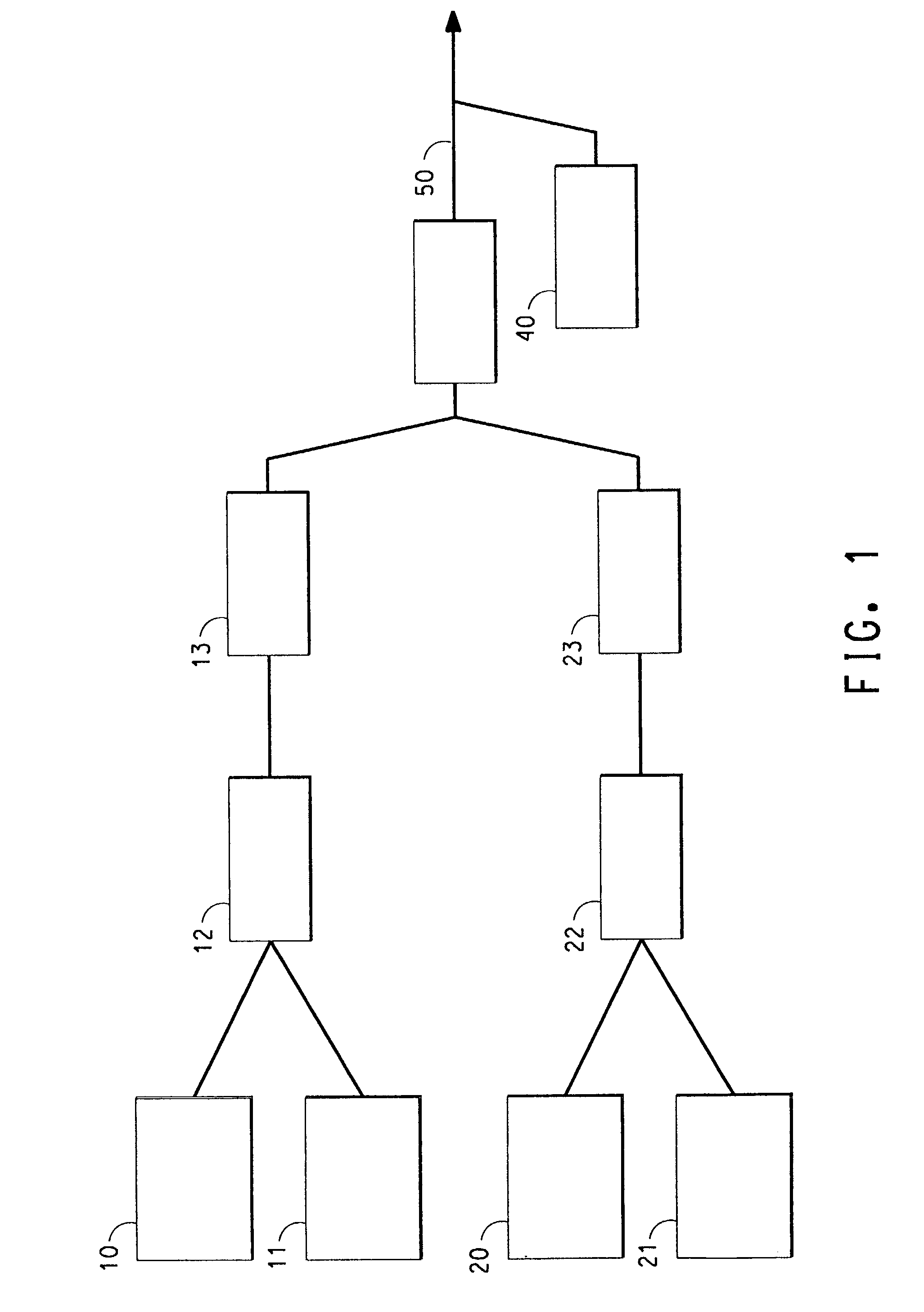
The present invention is about a process for making a multilayer structure by combining materials in separate layers and fusing them to form a plastically formable mass. This mass is then forced through a die onto a support to form a multilayer structure. The process minimizes exposure of the components to shear and elevated temperatures, and can produce structures with improved properties. The invention also includes a multislot die that allows for the simultaneous extrusion of materials from multiple extruders. The composition of at least one layer can include electrochemically active materials, electrically conductive materials, and ionically conductive mixtures.

Problems solved by technology

However, solvent coating has process limitations resulting in defects such as bubbles due to high drying rates; pinholes due to entrapped air or surface tension defects; settling of suspended solids during solution storage or handling; flooding and floating of suspended solids during drying; gelation of thermodynamically unstable solutions; and cracking due to shrinkage stresses during drying.
On the other hand, a disadvantage to extrusion, as practiced in the existing art, is the requirement of melting the polymer at relatively high temperatures, making it difficult to process any volatile liquids or thermally unstable materials.
Another disadvantage to extrusion as practiced in the existing art, is that mixing is carried out in the molten state, imposing high shear stresses on the mixtures.
This can cause degradation of some of the desired properties of the composition.

Method used


Image

  • Multilayer structure including an active electrochemical material and ionic polymer in a electrochemical cell
  • Multilayer structure including an active electrochemical material and ionic polymer in a electrochemical cell

Examples


example 1

[0091]This example illustrates the improved electrical conductivity of layers in which the components are combined to form a macroscopically homogeneous mass prior to fusing.

[0092]A cathode layer was made with the composition given in Table 1 below:

[0093]

TABLE 1COMPOSITIONCathode% by weightpVDF-HFP9.6LiCoO262.7carbon black 26.3EC10.7PC10.7

[0094]The lithium cobalt oxide was added to a 5 gallon (19 liter) container. One-third of the EC / PC liquid was sprayed into the container with the LiCoO2 and tumbled for 5 minutes using a Morse Drum Tumbler, Model 2-305-A, made by Morse, East Syracuse, N.Y. A second third of the EC / PC liquid was added and tumbled for another 5 minutes. The final third of the EC / PC liquid was added and tumbled for 5 minutes. Finally the pVDF-HFP and carbon black were added to the container and tumbled for 5 minutes. At the end of this time, the mixture had the appearance of black talc.

[0095]The blend was added to the hopper of a single screw extruder with a twin scr...

example 2

[0101]This example illustrates the formation of a multilayer structure by multilayer extrusion coating with a multislot die. The structure will have a separator layer on an anode layer on a copper foil current collector.

[0102]The layers will have the compositions listed in Table 3 below:

[0103]

TABLE 3COMPOSITIONSAnode% by weightpVDF-HFP7.0EC / PC (1:1)25.0graphite65.0carbon black 23.0Separator% by weightpVDF-HFP33.0EC / PC (1:1)45.0silica22.0

[0104]The macroscopically homogeneous anode mixture will be prepared in a manner similar to the cathode in Example 1, resulting in a mass made up of sand-like particulate solids. The macroscopically homogeneous separator mixture will be similarly treated, resulting in a mass made up of sand-like particulate solids.

[0105]The anode mixture will be extruded using conditions similar to those described in Example 1. The separator mixture will be extruded using conditions similar to those described in Example 1. In the extruders, the components will be fus...

example 4

[0106]This example illustrates the formation of a multilayer structure by multilayer co-extrusion coating with a multi-manifold single-slot die. The structure will have a separator layer on an anode layer on a copper foil current collector.

[0107]The layers will have the same compositions as in Example 2. The components for each layer will be mixed and introduced into separate extruders as described in Example 2. The extrusion conditions will be the same as in Example 2. The extrudates will be fed into a multi-manifold, single-slot die, such as that which is available from Cloeren Inc., Orange, Tex. The anode and separator materials will be extruded through the die onto a casting roll and laminated to copper foil as described in Example 2. The resulting multilayer structure will have an anode layer with a thickness in the range of 100–200 microns and a separator layer with a thickness in the range of 30–60 microns.


PUM

PropertyMeasurementUnit
thicknessaaaaaaaaaa
temperatureaaaaaaaaaa

Abstract

Multilayer articles, particularly multilayer articles having electrical or ionic conductivity, are made using an improved melt extrusion process. The process includes a combination step in which a macroscopically homogeneous mass is formed prior to introduction into an extruder. The multilayer article may include an electrode layer and a separator layer that are extruded onto a metal current collector. Such structures are particularly useful in lithium-ion batteries.

Description

[0001]This is a division of application Ser. No. 09 / 517,298, filed on Mar. 2, 2000, now U.S. Pat. No. 6,503,432.BACKGROUND OF THE INVENTION[0002]1. Field of the Invention[0003]The present invention relates to a melt extrusion process for making multilayer articles, particularly multilayer articles having electrical or ionic conductivity. The articles are suitable for use in electrochemical applications, such as batteries, fuel cells, electrolysis cells, ion exchange membranes, sensors, electrochemical capacitors, electrochromic windows, and modified electrodes. Of particular interest is the use in lithium-ion batteries.[0004]2. Description of the Related Art[0005]A battery can be made of one or more cells, usually connected to achieve a particular voltage and / or capacity. A cell includes three major components: the positive electrode, the negative electrode, and an electrolyte. A porous, polyolefin-based separator is also commonly present to prevent electrical contact between the tw...

Claims


Application Information

Patent Timeline
Patent Type & Authority Patents(United States)
IPC IPC(8): H01M4/04H01M4/62B29C48/08H01M6/18H01M6/40H01M10/04H01M10/0525H01M10/0565H01M10/0585H01M10/36
CPCB29C47/145H01M4/621H01M4/623H01M10/0436B29C47/065B29C47/0021Y10T29/49112B29L2031/3468H01M4/625H01M6/181H01M6/188H01M6/40H01M10/0525H01M10/0565H01M10/0585Y10T29/49115B29C48/08B29C48/21B29C48/307Y02E60/10Y02P70/50
Inventor BARTON, KELLY D.GRAY, DONALD G.ROCKWELL, GUY E.
Owner EI DU PONT DE NEMOURS & CO
Learn More