Optical communication apparatus

a technology of optical communication and optical fiber, which is applied in the direction of transmission monitoring, instruments, transportation and packaging, etc., can solve the problems of increasing the transmission loss of plastic optical fiber, increasing the wavelength of emitted light, and prone to variation in the wavelength of light emitted from a light source, so as to achieve long-distance transmission and excellent heat resistance

Inactive Publication Date: 2006-05-02
MITSUBISHI RAYON CO LTD
View PDF10 Cites 10 Cited by
  • Summary
  • Abstract
  • Description
  • Claims
  • Application Information

AI Technical Summary

Benefits of technology

[0010]The present invention has been implemented in view of the problem of the conventional techniques as described above, and has an object to provide an optical communication apparatus using a plastic optical fiber which has excellent heat resistance and can perform long-distance transmission.

Problems solved by technology

In the conventional optical communication apparatus using a red light-emitting diode and a plastic optical fiber having a core made of polymethylmethacrylate resin as described above, the wavelength of light emitted from a light source is liable to vary due to temperature variation, and the variation of the wavelength of the emitted light sharply increases transmission loss of the plastic optical fiber.
Therefore, the transmission loss is increased and thus it is difficult to perform long-distance optical communication (transmission).
However, when this light source is used in combination with a plastic optical fiber, the heat resistance of the plastic optical fiber becomes lower.
However, in the conventional plastic optical fiber, electron transition absorption due to thermal oxidation deterioration of the optical fiber more remarkably occurs to light having shorter wavelength, and thus the transmission loss is more greatly increased in the blue region.
However, this optical transceiver carries out the bi-directional communications through a single core, and thus it does not aim at long-distance transmission.
Therefore, it has a drawback that S / N is too low to carry out the long-distance optical transmission.
Still further, the optical communication apparatus disclosed in JP(A)-8-116309 and the optical transceiver disclosed in JP(A)-9-318853 are not suitable for long-distance transmission because the optical fibers used in these apparatuses are not suitable for optical transmission in a short-wavelength range such as blue, yellow, etc.

Method used


Image

  • Optical communication apparatus
  • Optical communication apparatus
  • Optical communication apparatus

Examples


example 1

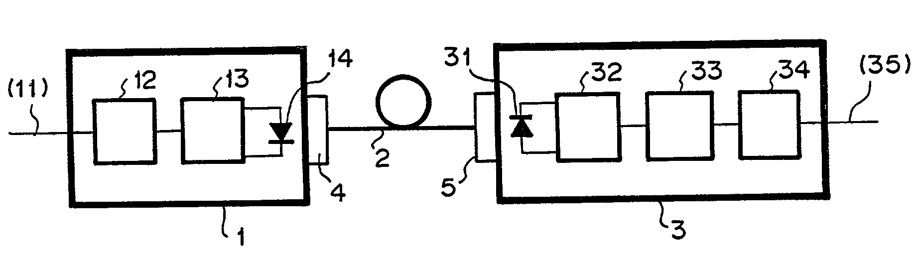
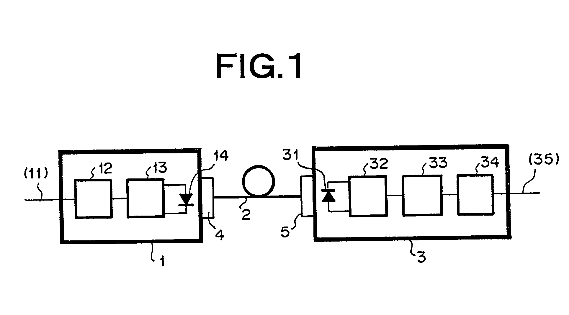
[0072]The optical communication apparatus shown in FIG. 1 was disposed in a thermostat, and the temperature characteristic at the transmission level was measured. FIG. 4 shows the result thereof. In FIG. 4, the light amount level at a temperature of 25° C. is indicated as 0 dB. In the optical communication apparatus used, it was confirmed that the transmission level was stable in a broad temperature range of 0 to 85° C. and the heat resistance was excellent.

[0073]Next, the transmission loss characteristic of the plastic optical fiber 2 used for the optical communication apparatus at 85° C. under a dry condition was measured with respect to the time. As a result, no increase of the transmission loss at 570 nm in wavelength was observed after 1000 hours.

[0074]From the above result, it was found that in the optical communication apparatus used in Example 1, both the light-emitting element and the optical fiber had excellent heat resistance, and 300 m long-distance transmission could be...

example 2

[0075]The optical communication apparatus was designed in the same construction as Example 1 except that a green light emission diode was used in place of the yellow light emission diode 14.

[0076]The green light emission diode used was based on InGaN type, and at the current value of 20 mA, the maximum light emission wavelength was equal to 525 nm, the full width at half maximum was equal to 20 nm, and the total emitted light amount was equal to 3 dB. The average transmission level of the optical transmitter 1 was equal to −7 dBm. The average minimum photodetecting sensitivity of the optical receiver 3 satisfying BER of 10−7 or less in the 20 kbps NRZ signal transmission was equal to −41.0 dB at the wavelength of 525 nm.

[0077]Like Example 1, the heat resistance test of the optical communication apparatus was carried out. FIG. 4 shows the result thereof. In the optical communication apparatus used in Example 2, it was found that the transmission level was stable in a broad temperatur...

example 3

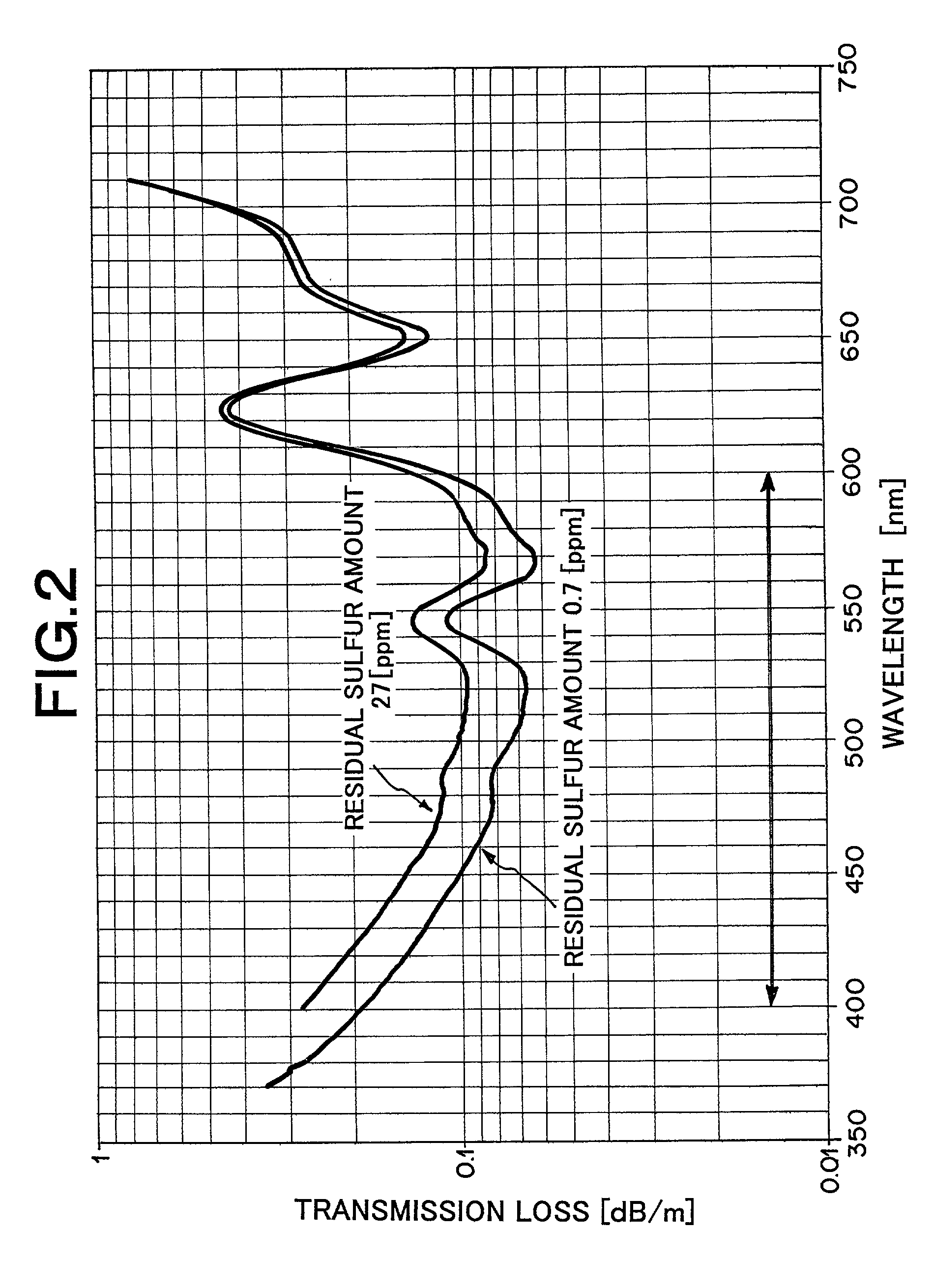
[0080]The optical communication apparatus was designed in the same construction as Example 1 except for use of a plastic optical fiber 2 in which the residual sulfur amount in the core was equal to 27 ppm and the content of sulfur atoms bound to the polymer was equal to 590 ppm (the wavelength-dependence of the transmission loss is shown in FIG. 2).

[0081]The transmission loss measured with collimated light at the wavelength of 570 nm was equal to 0.09 dB / m. The transmission loss when the optical transmitter 1 was connected was increased up to 0.13 dB / m because the loss due to the spreading of the wavelength of the yellow light-emitting diode 14 and increase of loss caused by higher mode components.

[0082]Like Example 1, the transmission loss characteristic of the plastic optical fiber 2 was measured with respect to the time. As a result, an increase of the transmission loss of about 0.005 dB / m at the wavelength of 570 nm was observed after 1000 hours.

[0083]From the above result, the ...


PUM

PropertyMeasurementUnit
light emission wavelengthaaaaaaaaaa

Abstract

An optical communication apparatus comprises an optical transmitter (1) which emits light signals corresponding to external electric signals (11) using light emitted from a short-wavelength light-emitting element (14) such as a yellow light-emitting diode of maximum wavelength in a range of 560–590 nm or a green light-emitting diode of maximum wavelength in a range of 490–550 nm; a plastic fiber (2) including a methacrylate polymer core free from benzene rings and having one end connected optically with the short-wavelength light-emitting element (14), the core containing less than 5 ppm free sulfur; and an optical receiver (3) having a photodetector element (31) connected optically with the other end of the plastic fiber (2) and adapted to producing an output electric signal (35) in accordance with the output from the photodetector element (31).

Description

TECHNICAL FIELD[0001]The present invention relates to a technique for optical communication using a plastic optical fiber, and particularly to an optical communication apparatus aiming to enhance heat resistance and perform long-distance communication.BACKGROUND TECHNIQUE[0002]Following recent increasing demands of optical communications using plastic optical fibers such as LAN, etc., increase in the communication distance and enhancement of resistance to environments, particularly resistance to heat (which means that the transmission characteristic is not varied with respect to the temperature variation) have been required.[0003]A plastic optical fiber having a core made of methyl methacrylate polymer has been widely used as an optical transmission path for optical communications because it has advantages such as low absorbance, etc. A red light-emitting diode is generally used in an optical communication apparatus using such a plastic optical fiber as an optical transmission path....

Claims


Application Information

Patent Timeline
Patent Type & Authority Patents(United States)
IPC IPC(8): H04B10/12H04B10/50
CPCG02B6/02033H04B10/502Y10T428/2967Y10T428/2938Y10T428/2929Y10T428/2933G02B1/046C08L33/12H04B10/25H04B10/50H04B10/60
Inventor YOSHIMURA, TOMONARISAITO, NORITAKAOKITA, AKIMITSU
Owner MITSUBISHI RAYON CO LTD
Why Eureka
Try Eureka