Multi-layer capacitive transducer

a capacitive transducer and multi-layer technology, applied in the direction of variable capacitors, capacitors with temperature varied dielectrics, instruments, etc., can solve the problems of sudden bulging of springs sideways, insufficient thickness to provide optimal resistance to sideways rocking, etc., to achieve easy measurement, eliminate errors, and increase alignment accuracy

Inactive Publication Date: 2006-05-16
BONIN WAYNE
View PDF19 Cites 25 Cited by
  • Summary
  • Abstract
  • Description
  • Claims
  • Application Information

AI Technical Summary

Benefits of technology

[0019]The transducer of the current invention has been fabricated with a moving mass of 46 mg including the 17 mg probe tip, which is 5 times lower than the prior art transducer. The mass reduction was achieved by using 25 μm thick pickup electrode skins that were partially etched to about 7 μm thick on the inner surface to reduce the thickness even further. The core thickness was 75 μm. The 125 μm total thickness of the moving electrode assembly, or rotor, is enough to provide a very rigid, flat assembly, but is not thick enough to provide optimal resistance to sideways rocking. Resistance to sideways rocking is provided by using two rotor plates, spaced apart by 1.5 to 2 mm, and connected to each other by a lightweight, rigid tubular stem. This provides significantly more resistance to sideways forces than the prior art transducer, while at the same time reducing the moving rotor mass as well. The moving electrode assembly of the current transducer is referred to as the rotor, since the moving electrode is not necessarily the pickup electrode.
[0021]Etched alignment features in the metal layers of the current transducer greatly increase the alignment accuracy between the various layers. This is especially critical for the rotor plates. In the prior art transducer, the etched features in the core had a width of over 500 μm, partly required due to the errors of up to 100 μm present in aligning the skins to the core during the bonding of the rotor plates. In the current transducer, the etched alignment features reduced the assembly alignment error to less than 10 μm. Etched features in the core and inner side of the electrode skins of 125 μm presented no problems. It appears that 75 or even 50 μm features are feasible.
[0022]The inclusion of two separate rotor plates allowed the position sensing function and the electrostatic actuation function to be isolated from each other, eliminating the possibility of destruction of the oscillator and / or signal detector by the electrostatic actuation voltage. A further related advantage is that the electrostatic actuation voltage is now applied directly to the appropriate transducer electrode, eliminating the errors caused by the buffer elements of the prior art transducer. Since the electrostatic voltage applied to the transducer is the same as the output of the electrostatic controller, it can now be easily measured by utilizing the resistive voltage divider normally included in the controller.
[0023]The problem of hysteresis and creep present in the prior art transducer was solved by incorporating a stress distribution feature into the joint design at the base of the springs, so that the maximum stress in the bond is reduced by a factor of 10.
[0024]Another improvement over the prior art transducer is in using small press in electrical interconnection pins that mate with receptacles in the drive circuit board to connect the transducer to the drive circuit. This is both more convenient than soldering to the tabs of the prior art transducer, and also provides better performance as the electrical interconnection is now smaller and better shielded by the grounded layers inside the transducer, whereas the connections in the prior art transducer were larger and completely exposed on the outside of the transducer, rendering them vulnerable to corruption by external noise sources.

Problems solved by technology

The 125 μm total thickness of the moving electrode assembly, or rotor, is enough to provide a very rigid, flat assembly, but is not thick enough to provide optimal resistance to sideways rocking.
In the prior art transducer it was not possible to use rotor plate skins with a thickness as small as 25 μm, due to buckling of the springs (the thickness of the springs is the same as the thickness of the electrode skin, as they are etched from the same metal foil).
When the critical value is exceeded, the spring suddenly bulges out sideways, and no longer provides the stable, well defined support required.
The source of the buckling load is due to mismatches of TCE of the transducer materials, creating locked in stress from the epoxy curing process which bonds the layers of the transducer together.
Even if there is no locked in stress from the transducer manufacturing operation, side loads can also cause buckling, as they will place half of the springs in compression.

Method used


Image

  • Multi-layer capacitive transducer
  • Multi-layer capacitive transducer
  • Multi-layer capacitive transducer

Examples


first embodiment

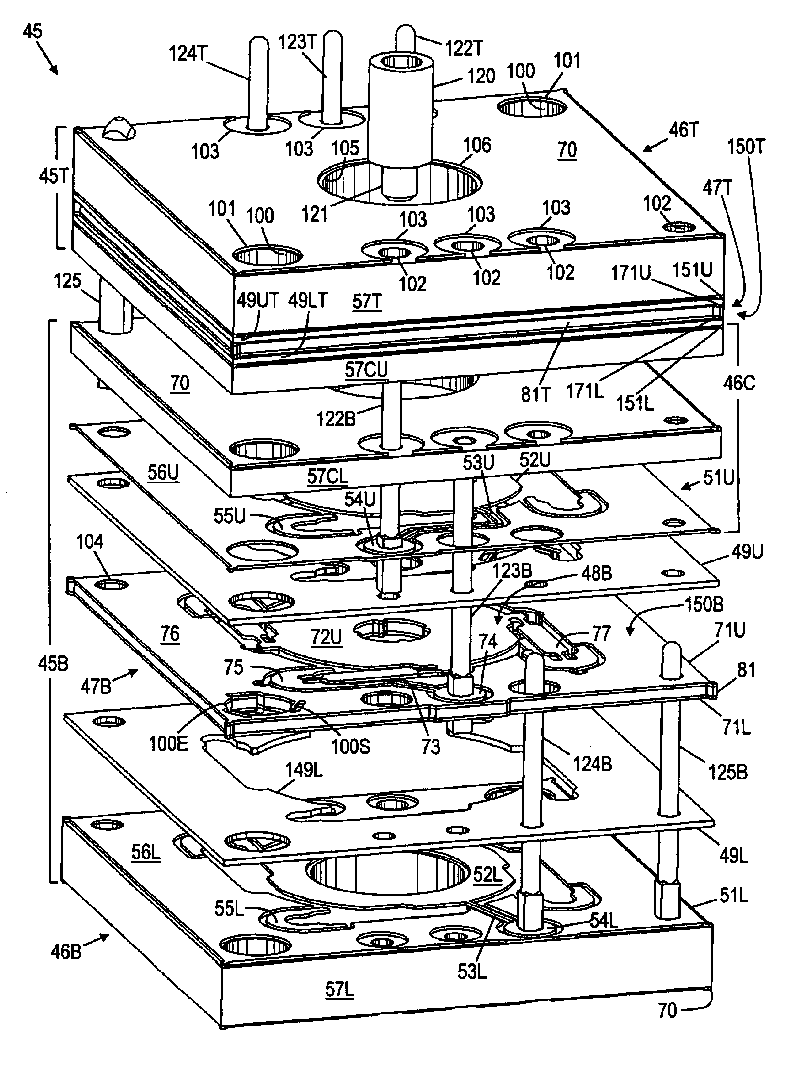
[0091]Rotor core layer 281 (FIG. 17) has rotor core 90 and tabs 89 which are the same as in the Rotor core frame 286 has the same features as rotor plate skin layer 276.

[0092]Pickup electrode layer 251L (FIG. 18) is similar to lower drive electrode layer 51L of the first embodiment. Since the rotor plates are grounded and isolated spring anchors are not required, supports 55L are not isolated, and are incorporated into frame 256L. Pickup electrode 252L is the same shape as drive electrode 52L, but is located above rotor plate 48B. Trace 253L connects electrode 252L to pad 254L, which is connected to front center electrical interconnect pin 123B (FIG. 4). Hole 102 for pin 123B is not shown in pad 254L in FIG. 18, as holes 102 are drilled through the entire transducer after the final assembly. As in the first embodiment if the substrate material is G-10 printed circuit board laminate, layer 251L, as well as shields 70 and other stator (non-rotor) electrodes are preferably made of cop...

third embodiment

[0099]A third embodiment, optimized for significantly higher loads, will now be described. The specified dimensions are for a transducer with a load capacity of 1000 grams. Since this is currently significantly greater than the force that can be generated by electrostatic actuation, this embodiment is shown without the electrostatic actuation drive electrodes. The top section includes the drive electrode, pickup electrode, and rotor plate, which may function directly as a target electrode for position sensing (which the stiffness of the springs converts to force sensing), or a separate unstressed target electrode may be added in addition to the rotor plate, for better linearity. The bottom section includes the rotor plate layer without position sensing electrodes, to constrain the motion to the vertical axis only, so that off center or off axis loads do not result in excessive errors in the measurements. Position sensing electrodes could be included in the lower section as well, whi...

second embodiment

[0105]Upper gap spacer 660 (FIG. 31), positioned immediately above rotor plate layer 650, provides space for target electrode 642 and rotor plate 652 to move in the upwards direction. Space in the downwards direction is provided by spacer 630. Spacer 660 includes frame 661, with inner opening 666. The shape of inner opening 666 is selected so that frame 661 provides optimal support to rotor plate layer 650, without interfering in the motion of springs 659 or plate 652. Alignment holes 500E are used in the assembly process. Spacer 660 is preferably constructed of metal, such as brass, and may be 0.016 inch thick. Lower gap spacer 630 may be constructed of G-10 printed circuit board substrate material, and may have a thickness of about 0.01 inch. As shown in FIG. 28, spacer 630 must be constructed of an electrically insulating material to prevent shorting the pickup signal on trace 623 and pad 624 to ground. If isolation channels such as those included in spacer 349L of the second emb...


PUM


Abstract

A capacitive transducer of multi-layer construction includes two rotor plates supported by flexible springs, the plates being spaced apart and rigidly connected by a stem. One rotor plate my be used as either a pickup electrode or a grounded target electrode for determining position, displacement, or load force. The second rotor plate may be used for electrostatic actuation without interfering with or destroying circuitry associated with the first rotor plate. A number of improvements are disclosed including a hollow rotor plate structure for reduced moving mass, buckling resistant features for the springs, improved spring anchor joint design for reduced creep and hysteresis, and material selection and matching for reduced thermal sensitivity.

Description

CROSS-REFERENCE TO RELATED APPLICATIONS[0001]This application claims the benefit of PPA Ser. No. 60 / 470,774, filed May 15, 2003 by the present inventor.STATEMENT REGARDING FEDERALLY SPONSORED RESEARCH OR DEVELOPMENT[0002]Not ApplicableREFERENCE TO SEQUENCE LISTING, A TABLE, OR A COMPUTER PROGRAM LISTING COMPACT DISK APPENDIX[0003]Not ApplicableBACKGROUND OF THE INVENTION[0004]This invention relates to capacitive transducers, for example for use in displacement and force-responsive devices.[0005]Capacitive transducers use various configurations of capacitor electrodes along with springs, diaphragms or other support mechanisms to sense acceleration, force, weight, pressure, displacement or position. Capacitive transducers have much higher output signal than strain gauge transducers, giving them a significant advantage in signal to noise ratio (SNR) and reduced susceptibility to drift from offset voltages in the circuitry, and thermocouple effects in the wiring, but capacitive transduc...

Claims


Application Information

Patent Timeline
Patent Type & Authority Patents(United States)
IPC IPC(8): H01G5/16
CPCH01G5/14G01D5/2417
Inventor BONIN, WAYNE ALLEN
Owner BONIN WAYNE
Why Eureka
Try Eureka