Lithographic apparatus, device manufacturing method, performance measuring method, calibration method and computer program

a technology of lithographic projection and manufacturing method, which is applied in the field of lithographic projection apparatus, a device manufacturing method, a performance measurement method, a calibration method and a computer program, can solve the problems of large transient oscillation of pulse energy, complex control system, and complex devices used in excision lasers at present, and achieve the effect of more accurate dose control

Active Publication Date: 2006-06-06
ASML NETHERLANDS BV
View PDF3 Cites 18 Cited by
  • Summary
  • Abstract
  • Description
  • Claims
  • Application Information

AI Technical Summary

Benefits of technology

[0015]It is an aspect of the present invention to provide a lithographic apparatus capable of more accurate dose control. It is a further aspect of the invention to provide methods of measuring the performance of a pulsed radiation source in a lithographic apparatus and methods of calibrating the control system of the radiation source, even during exposures.

Problems solved by technology

Excimer lasers used at present are complex devices and exhibit complex behavior under control.
In particular, step changes in operating parameters, e.g. when the laser is turned on at the beginning of an exposure or series of exposures or when there is a change in pulse repetition rate or excitation voltage, result in large transient oscillations of the pulse energy.
To avoid variations in the dose delivered at substrate level, the control system for the laser must take account of such transients and other complex behaviors of the laser, resulting in a necessarily complex control system.
Fine tuning the parameters of the laser control system is difficult and it is particularly difficult to take account of time varying effects, e.g. gas aging in the laser cavity.
However, such measurements cannot be made during exposures and so the time taken for them reduces machine throughput.
Therefore it takes a long time, many exposures, to gather the necessary information in order to calibrate the pulse-energy / high-voltage gain.

Method used


Image

  • Lithographic apparatus, device manufacturing method, performance measuring method, calibration method and computer program
  • Lithographic apparatus, device manufacturing method, performance measuring method, calibration method and computer program
  • Lithographic apparatus, device manufacturing method, performance measuring method, calibration method and computer program

Examples


first embodiment

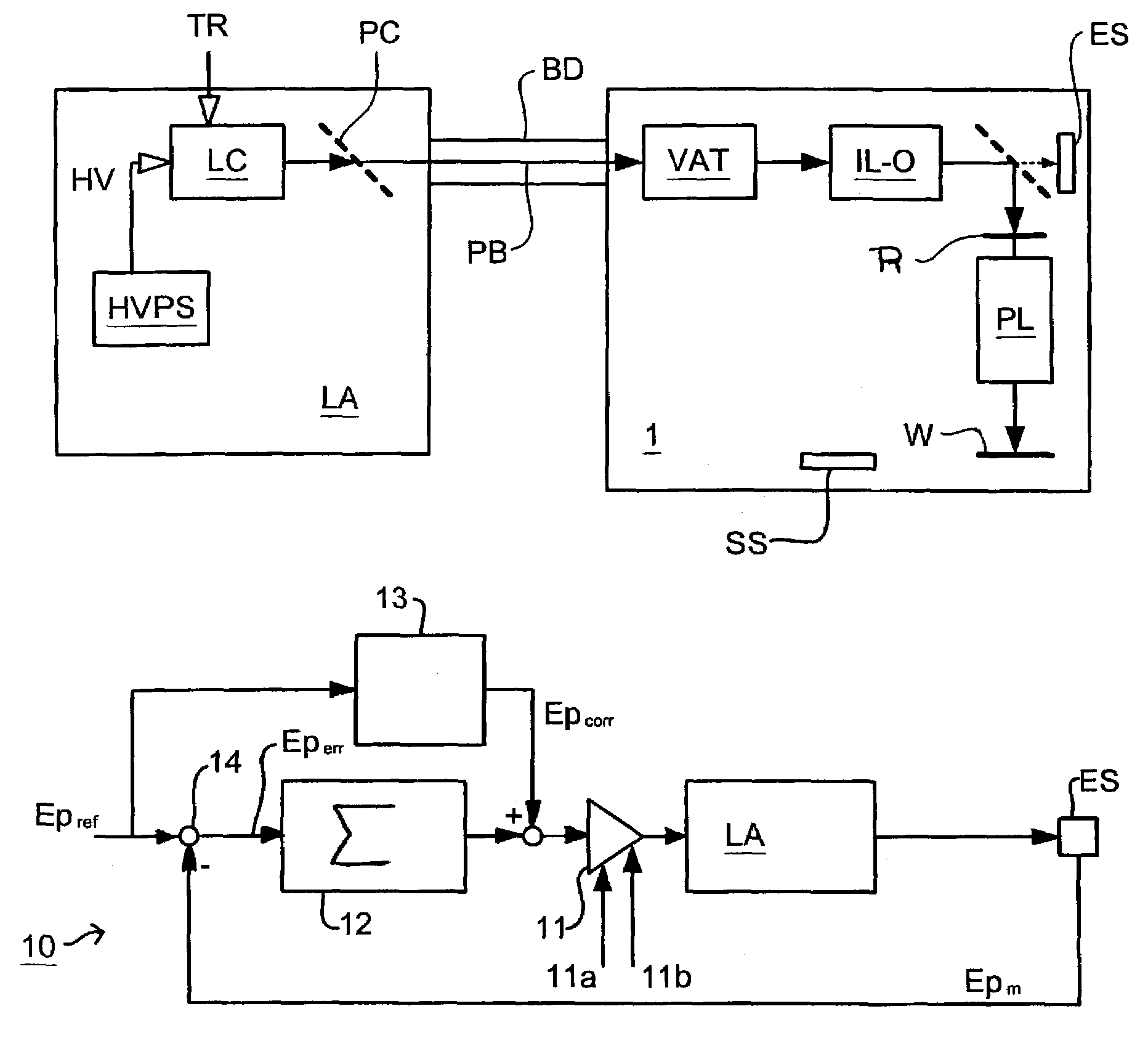
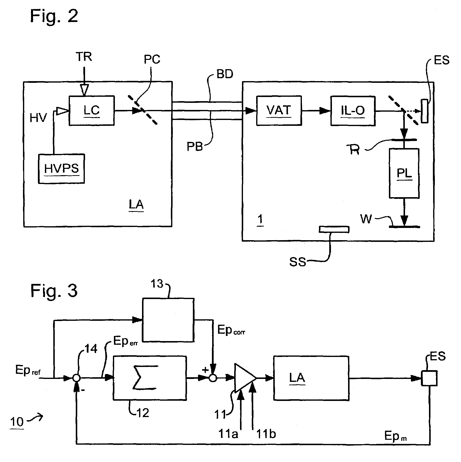
[0045]FIG. 3 depicts the integrated control system 10 of the present invention. In this system the variable attenuator VAT is set to a fixed degree of attenuation and is omitted from the drawing for clarity. The control system 10 has as input a desired pulse energy Epref, acting as a pulse energy set point. From this subtractor 14 subtracts the pulse energy Epm, of the previous pulse as measured by energy sensor ES to give the pulse energy error Eperr, and supplies its output to a simple summator 12. An amplifier 11 applies a gain and offset to the summated pulse energy error Eperr, representing the HV-Ep transfer function. The output of amplifier 11 determines the high voltage applied to the laser LA and hence the output pulse energy. The summator 12 may be implemented as a backward Euler discrete time approximation of an integrator Tz / (z−1), with a normalized gain of 1 / T (due to the repetition rate independence of the radiation source model). The above described components form a ...

second embodiment

[0054]the invention has an integrated control system as shown in FIG. 5. This control system uses a controller 20 to provide a closed loop feedback control based on the pulse energy as measured by the energy sensor ES. Controller 20 operates a control strategy incorporating an algorithm to calculate the target energy per pulse to deliver the desired dose at substrate level and to compensate for errors in previous pulse energies in subsequent pulses as well as an algorithm to calculate the excitation voltage HV that must be applied to the laser cavity LC to deliver a pulse of required energy. The control algorithm may also incorporate feed-forward algorithms to compensate for disturbance effects in the laser and predicted and other effects, e.g. due to lens heating, occurring downstream of the energy sensor ES. The controller 20 may also control the variable attenuator VAT. The variable attenuator VAT can be used when the required amplitude variation of Ep is large enough to cause th...


PUM

PropertyMeasurementUnit
wavelengthaaaaaaaaaa

Abstract

A controller for a pulsed radiation source is a closed-loop controller of minimum order, preferably first, to effect dead beat control. Performance indicators for a pulsed radiation source in a lithographic apparatus are based on moving averages (MA) and moving standard deviations (MSD) of the error between target and actual pulse energies. The normalized indicators are given by:
MAE,n(xk)=1i=k-(Nslit-e-1)kEpref(i)·i=k-(Nslit-e-1)kEperr(i)(k=Nslit-eNscan),
wherein Epref(i) and Eperr(i) indicate reference energy per pulse and energy error per pulse for point i and
MSDE,n(xk)=1Nslit-e-1i=k-(Nslit-e-1)k[Eperr(i)Epref(i)-MAE,n(xk)]2(k=Nslit-eNscan).

Description

RELATED APPLICATION[0001]This application claims the benefit of priority to European Patent Application No. 02253303.8, filed May 10, 2002, the contents of which are herein incorporated by reference.BACKGROUND OF THE INVENTION[0002]1. Field of the Invention[0003]The present invention relates to a lithographic projection apparatus, a device manufacturing method, a performance measuring method, a calibration method and a computer program.[0004]2. Description of the Related Art[0005]The term “patterning device” as here employed should be broadly interpreted as referring to device that can be used to endow an incoming radiation beam with a patterned cross-section, corresponding to a pattern that is to be created in a target portion of the substrate. The term “light valve” can also be used in this context. Generally, the pattern will correspond to a particular functional layer in a device being created in the target portion, such as an integrated circuit or other device (see below). An e...

Claims


Application Information

Patent Timeline
Patent Type & Authority Patents(United States)
IPC IPC(8): G03B27/42G03F7/20G03B27/00H01L21/027H01S3/134H01S3/225
CPCG03F7/70041G03F7/70558H01S3/09702H01S3/225H01S3/134H01L21/027
Inventor HEINTZE, JOHANNES
Owner ASML NETHERLANDS BV
Why Eureka
Try Eureka