

Coated tool
a technology of coating tools and coatings, applied in the field of coating tools, can solve the problems of affecting the wear resistance of the coating film, prone to chipping at the cutting edge, etc., and achieve the effects of superior wear resistance, superior lubrication, and high hardness
- Summary
- Abstract
- Description
- Claims
- Application Information
AI Technical Summary
Benefits of technology
Problems solved by technology
Method used
Image

Examples
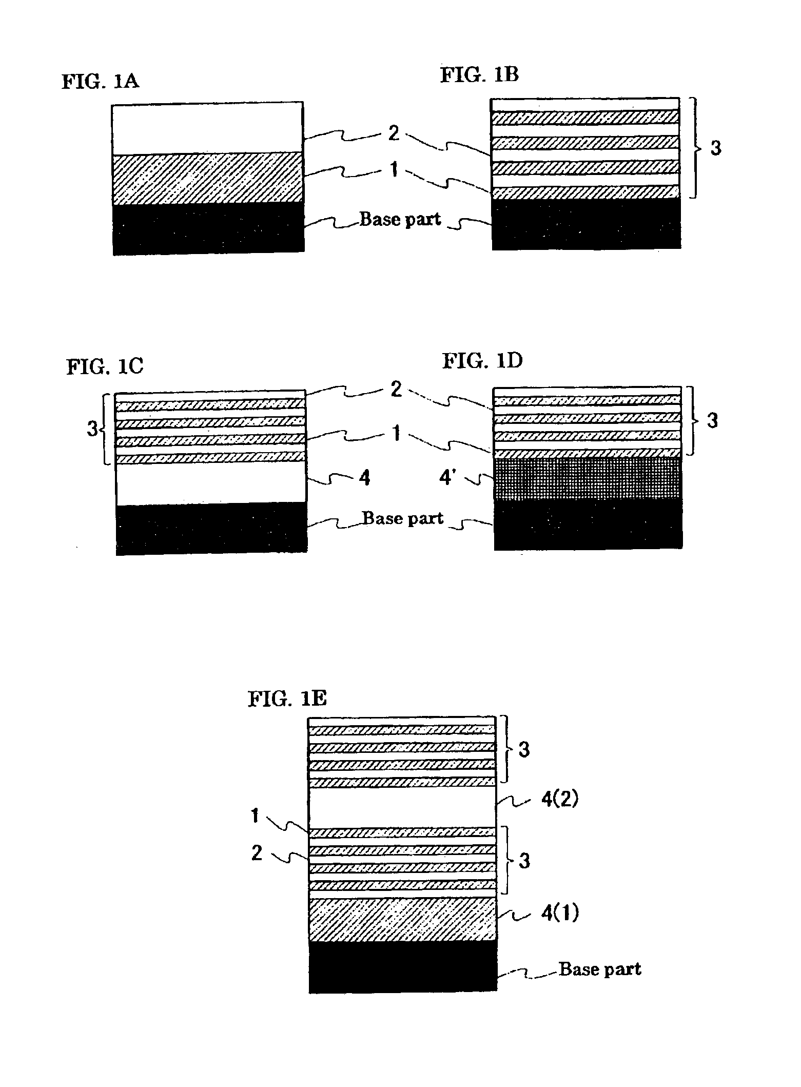
embodiment 1
(1) Test-Sample Fabrication
i. Present-Invention Products: Test Sample Nos. 1-1 Through 1-8
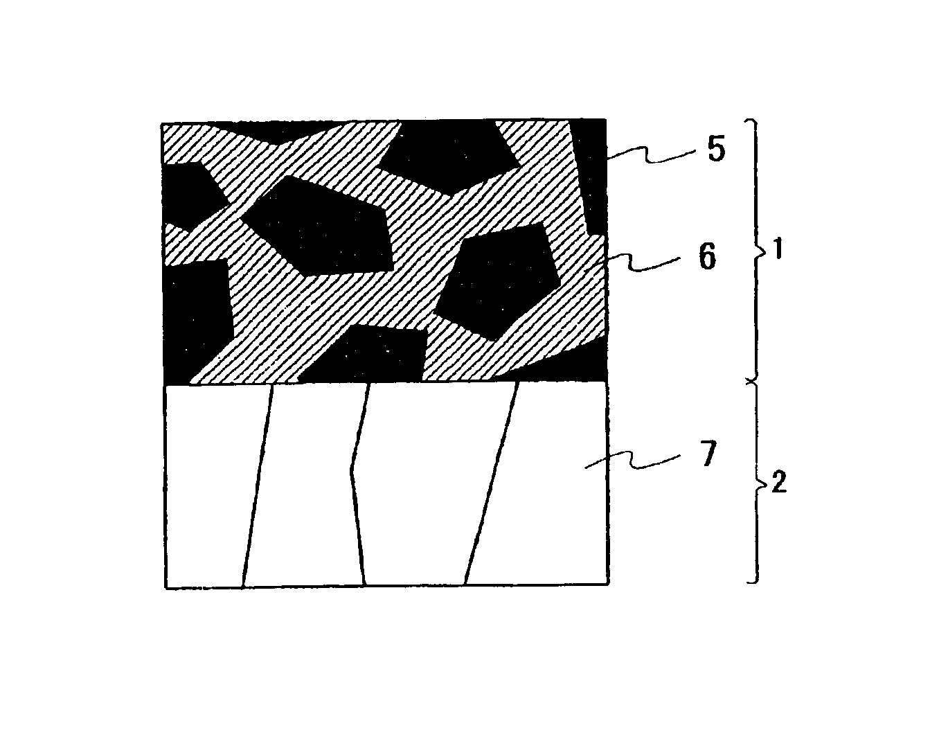
[0058]The film-deposition device utilized in the present test will first be explained. Reference is made to FIG. 3A, a schematic diagram of the film-deposition device utilized in the present test, and to FIG. 3B, a sectional view through B—B In FIG. 3A. The film-deposition device is in a chamber 12 equipped with: a main table 13 on which a substrate 19 is loaded and which is mounted rotatively on a support post 14; arc-evaporation sources 15a, 15b and 15c arranged along the walls of the chamber 12 so as to surround the substrate 19; dc-power supply 16a, 16b (not illustrated) and 16c as variable power supplies connected to the evaporation sources 15a, 15b and 15c; dc-power supply 17 connected to the main table 13; a gas introduction port 18 through which gas is supplied; and a gas discharge port 18′ through which gas is exhausted.
[0059]The chamber 12 is coupled to a vacuum pump (not illustrated)...
embodiment 2
[0077]Coatings were made on respective substrate reamers (of JIS K10 cemented carbide) according to the same manufacturing method as in Embodiment 1, whereby Test Sample Nos. 2-1 through 2-6 were produced. Test Sample No. 2-1 was furnished with the same intermediate layer and coating films as those of the foregoing Test Sample No. 1-1. For Test Sample No. 2-2, a 1 μm TiSiN film was coated onto the substrate surface, and onto this film the same coating films as those of the foregoing Test Sample No. 1-1 were furnished. For Test Sample No. 2-3, a 1 μm TiAlN film was coated onto the substrate surface, and onto this film the same coating films as those of the foregoing Test Sample No. 1-1 were furnished. For Test Sample Nos. 2-4 through 2-6, the same intermediate layer and coating films as those of the foregoing Test Sample Nos. 1-9 through 1-11 were furnished onto the respective substrates.
[0078]A drilling operation into gray iron (FC 250) was performed with these Test Sample Nos. 2-1 ...
embodiment 3
[0081]Coatings were made on respective substrate endmills (of JIS K10 cemented carbide) according to the same manufacturing method as in Embodiment 1, whereby Test Sample Nos. 3-1 through 3-6 were produced. Test Sample No. 3-1 was furnished with the same intermediate layer and coating films as those of the foregoing Test Sample No. 1-1. For Test Sample No. 3-2, a 1 μm TiSiN film was coated onto the substrate surface, and onto this film the same coating films as those of the foregoing Test Sample No. 1-1 were furnished. For Test Sample No. 3-3, a 1 μm TiAlN film was coated onto the substrate surface, and onto this film the same coating films as those of the foregoing Test Sample No. 1-1 were furnished. For Test Sample Nos. 3-4 through 3-6, the same intermediate layer and coating films as those of the foregoing Test Sample Nos. 1-9 through 1-11 were furnished onto the respective substrates.
[0082]An endmill horizontal cutting operation (cutting width 15 mm) into spheroidal graphite cas...
PUM
| Property | Measurement | Unit |
|---|---|---|
| thickness | aaaaa | aaaaa |
| thickness | aaaaa | aaaaa |
| thickness | aaaaa | aaaaa |
Abstract
Description
Claims
Application Information