High speed, silicon-based electro-optic modulator

Active Publication Date: 2006-06-20
CISCO TECH INC +1
View PDF12 Cites 55 Cited by
  • Summary
  • Abstract
  • Description
  • Claims
  • Application Information

AI Technical Summary

Benefits of technology

[0009]In accordance with the present invention, channel equalization is achieved by developing a doping profile for the device terminals that provides the desired limit of optical loss. For a given doping profile, there will be an associated maximum switching speed at which the modulator will function when using a simple drive circuit (i.e., a transition between two reference voltage levels, such as VDD and VSS, to switch between an optical “0” and an optical “1”). To increase the switching speed in accordance with the present invention, pre-emphasis voltages are applied during transitions between “1” and “0” (falling edge transitions), as well as between “0” and “1” (rising edge transitions), where the pre-emphasis voltage will accelerate charging and discharging of the MOSCAP (or modulator active capacitance), thus reducing the fall and rise times respectively between states. It should be understood that the output impedance of such pre-emphasis circuits should be as low as possible and in fact approach a voltage source for those modulators driven by voltage type signals. Therefore, the pre-emphasis circuits and techniques describe

Problems solved by technology

The disadvantage of this method is that when higher switching speeds are required, the dynamic behavior of the semiconductor material of the laser itself introduces distortion, primarily in the form of ch

Method used


Image

  • High speed, silicon-based electro-optic modulator
  • High speed, silicon-based electro-optic modulator
  • High speed, silicon-based electro-optic modulator

Examples


Embodiment Construction

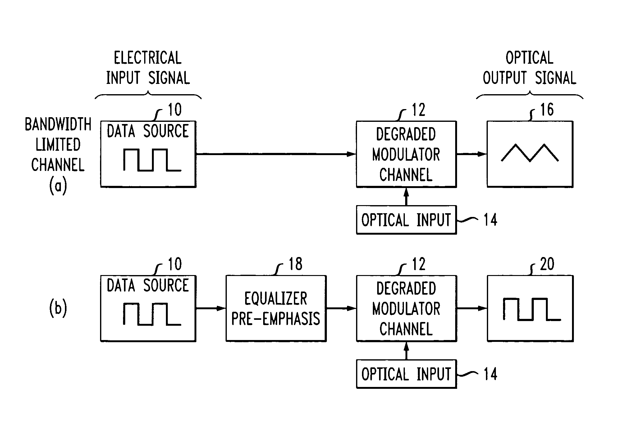
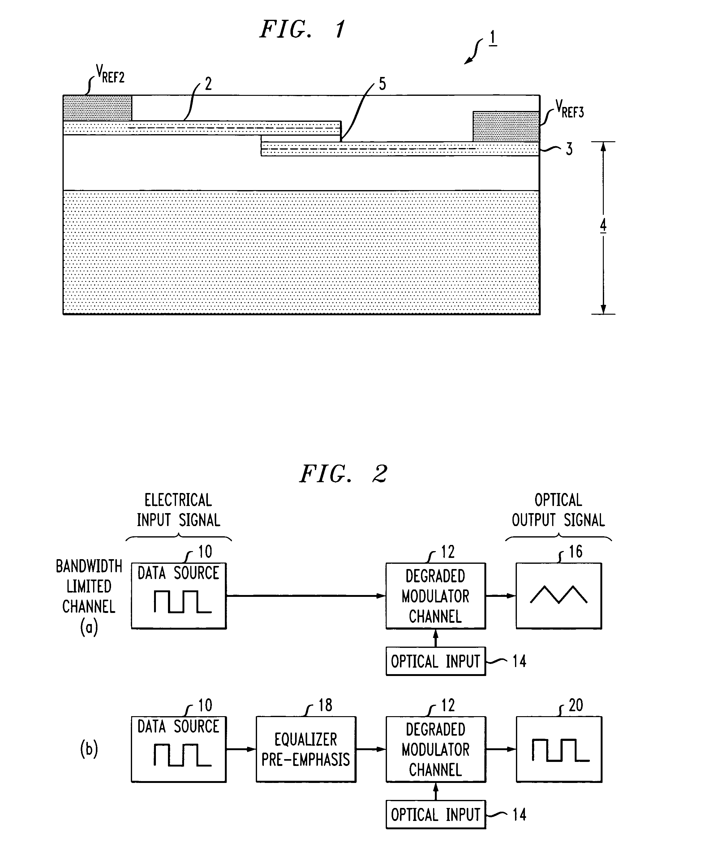
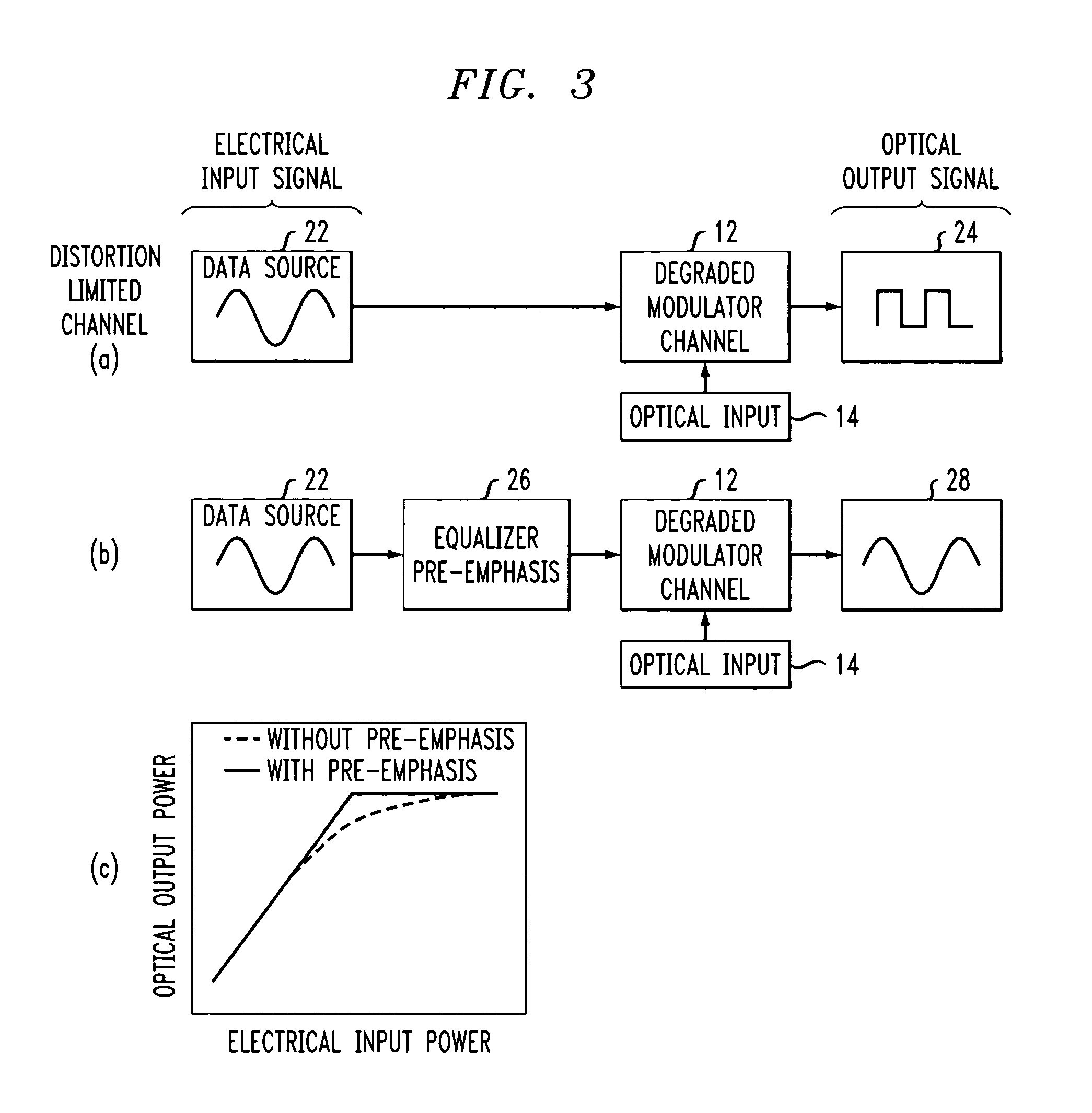
[0030]FIG. 2 illustrates, in simplified form, a nonlinear channel equalization arrangement showing the use of an equalizer / pre-emphasis circuit of the present invention to improve the optical output characteristics of a high speed optical modulator. FIG. 2(a) illustrates a bandwidth limited channel arrangement, where an electrical input data signal from a data source 10 is applied as the electrical input to a silicon-based modulator structure 12, such as the modulator illustrated in FIG. 1. It is to be understood that the theory of the present invention is equally applicable to any type of electrically driven optical modulator, that is, a modulator where the refractive index properties of an optical waveguide are changed by modulating an electrical input signal to produce a modified optical output signal. Such electro-optic modulators include, but are not limited to, free carrier-based modulators, particularly silicon-based electro-optic modulates.

[0031]Referring back to FIG. 2, an ...


PUM


Abstract

An electro-optic modulator arrangement for achieving switching speeds greater than 1 Gb/s utilizes pre-emphasis pulses to accelerate the change in refractive index of the optical waveguide used to form the electro-optic modulator. In one embodiment, a feedback loop may be added to use a portion of the modulated optical output signal to adjust the magnitude and duration of the pre-emphasis pulses, as well as the various reference levels used for modulated. For free carrier-based electro-optic modulators, including silicon-based electro-optic modulators, the pre-emphasis pulses are used to accelerate the movement of free carriers at the transitions between input signal data values.

Description

CROSS-REFERENCE TO RELATED APPLICATION[0001]This application claims the benefit of Provisional Application No. 60 / 468,885, filed May 8, 2003.TECHNICAL FIELD[0002]The present invention relates to silicon-based electro-optic modulators and, more particularly, to the provision of high speed (e.g., greater than 1 Gb / s) modulators by incorporating channel equalization techniques into the modulator and associated electronic drive circuit.BACKGROUND OF THE INVENTION[0003]Optical transmission systems are generally based on one of two methods of modulation of an optical signal, either direct modulation or external modulation. In the first of these methods, the bias current applied to a laser is modulated, turning the laser “on” and “off”. The disadvantage of this method is that when higher switching speeds are required, the dynamic behavior of the semiconductor material of the laser itself introduces distortion, primarily in the form of chirp. External modulation of an optical signal with a ...

Claims


Application Information

Patent Timeline
IPC IPC(8): H04B10/04G02B26/00G02F1/01G02F1/015G02F1/025G02F1/225
CPCG02F1/0121G02F1/025H04B10/58H04B10/505G02F2001/0152G02F1/225G02F1/0152G02B2006/12145G02F1/011
Inventor SHASTRI, KALPENDUGOTHOSKAR, PRAKASHGHIRON, MARGARETPATEL, VIPULKUMARMONTGOMERY, ROBERT KEITHPATHAK, SOHAMYANUSHEFSKI, KATHERINE A.
Owner CISCO TECH INC
Why Eureka
Try Eureka