Method of fabricating SOI wafer

a technology of soi wafers and soi layers, which is applied in the direction of basic electric elements, electrical apparatus, semiconductor devices, etc., can solve the problems of reducing the production yield, high density of crystal defects, and the aforementioned methods suffer from the drawbacks described, so as to reduce the surface roughness suppress the crystal defect and the soi layer surface roughness, and improve the film thickness distribution of the soi layer

Inactive Publication Date: 2006-08-01
SHIN-ETSU HANDOTAI CO LTD
View PDF18 Cites 43 Cited by
  • Summary
  • Abstract
  • Description
  • Claims
  • Application Information

AI Technical Summary

Benefits of technology

[0019]Thus-formed, etch-stoppable, ion-implanted layer is no more causative of broadening of the concentration profile of the etching-selectivity-providing component contained in the etch-stoppable, ion-implanted layer due to thermal diffusion, even for the case where high-temperature annealing is necessary in the bonding step, because the bonding annealing proceeded under high temperatures has already finished, and this successfully maintains a sharp concentration profile. Because the depth of ion implantation in the formation of the etch-stoppable, ion-implanted layer can exactly be reproduced if only the ion implantation energy is controlled at constant, so that in-plane variation of the depth of concentration peak of the etching-selectivity-providing component can also be minimized. The succeeding second thinning step based on selective etching is therefore successful in obtaining an SOI layer having an excellent film thickness distribution not only on the intra-wafer basis but also on the inter-wafer basis, corresponding to the sharp concentration profile having a constant depth of the peak position.
[0031]On the other hand, for the case where ELTRAN process is adopted, a porous silicon layer is formed on the first main surface side of the second substrate prior to the bonding step, and on the porous silicon layer, a silicon epitaxial layer intended for becoming the SOI layer is formed by vapor-phase epitaxy. The surface of the silicon epitaxial layer is then bonded to the first substrate. Thereafter, the silicon epitaxial layer intended for becoming the SOI layer is delaminated from the second substrate at the porous silicon layer, and the porous silicon layer remaining on the silicon epitaxial layer is removed by selective etching, to thereby form the SOI layer. As has already been described in the above, it is difficult to suppress the crystal defect and surface roughness of the SOI layer immediately after the selective etching of the porous silicon layer to as low as a sufficient level only by ELTRAN process, but combination with the succeeding second thinning step based on the selective etching is successful in sufficiently reducing these surface defects without adversely affecting the thickness distribution of the SOI layer.

Problems solved by technology

The aforementioned methods, however, suffers from drawbacks as described below.
In this case, the above-described level of non-uniformity in the film thickness accounts for as much as 10 to several ten percents of the target average film thickness, so that it is a matter of course that this directly results in quality variation of semiconductor devices using the SOI wafer, and lowering in the production yield.
Next, in the ELTRAN process ②, the finally obtained SOI layer is thinned by etch back of the porous Si layer, where a problem resides in that the SOI layer contains, in the surficial portion thereof, a high density of crystal defect such as stacking fault produced in the process of forming an epitaxial layer on the porous Si layer.
It is obvious in this case that any trial of touch polishing for removing the crystal defects in the surficial portion will result in the same problem with that in the Smart Cut Process ①.
This inevitably requires lowering of the bonding annealing temperature to as low as 800 to 900° C., where another problem arises in that it is made impossible to attain a sufficiently large bonding strength, and that a lot of unbonded areas, called voids, are generated, and that the bond interface becomes more likely to be eroded in the etch back process.

Method used


Image

  • Method of fabricating SOI wafer
  • Method of fabricating SOI wafer
  • Method of fabricating SOI wafer

Examples


first embodiment

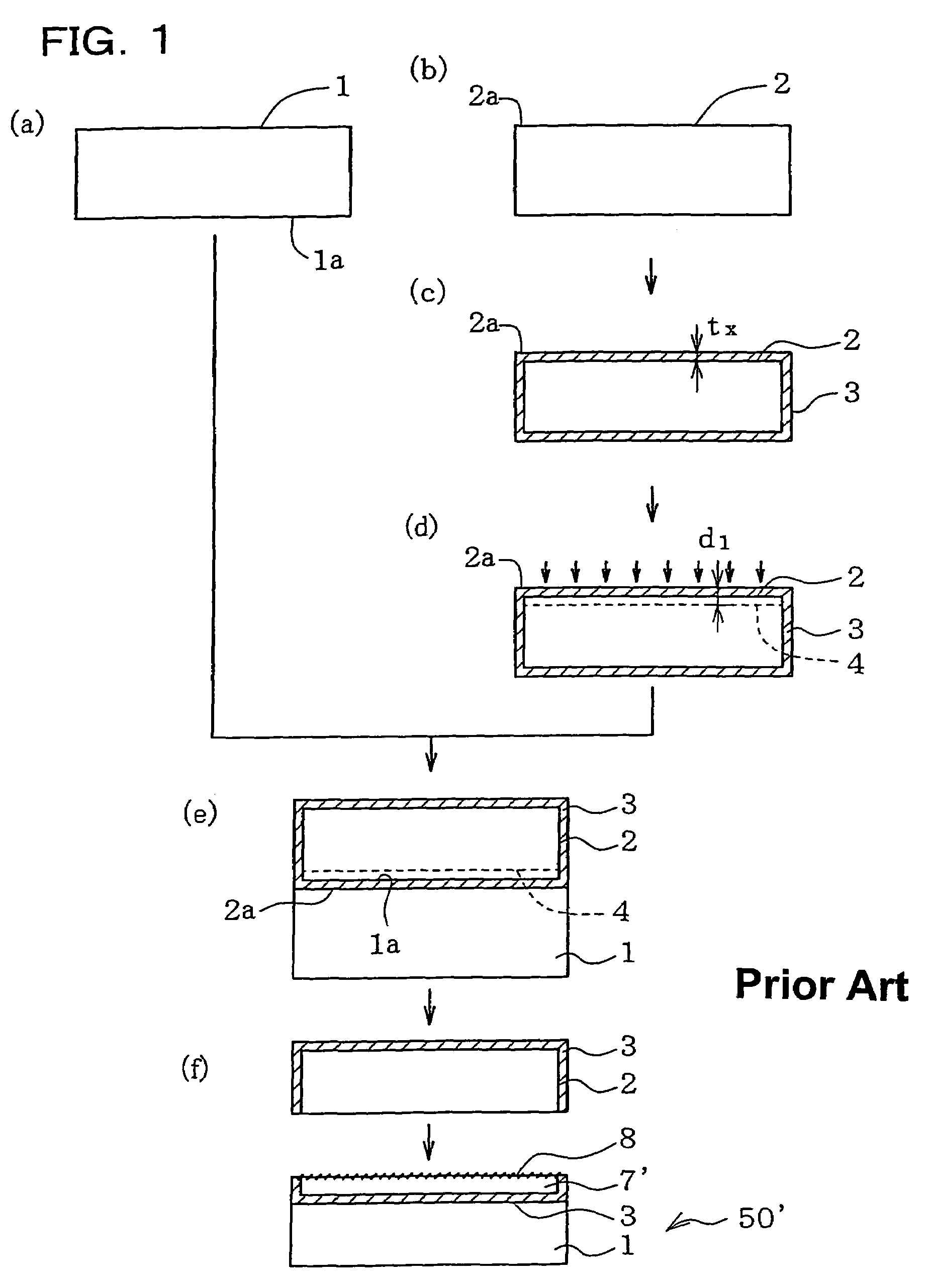
[0049]FIG. 1 is a drawing schematically explaining the method of fabricating an SOI wafer of this invention based on an exemplary case of using Smart Cut Process. First, a base wafer 1 (silicon single crystal wafer) as a first substrate shown in process step (a) and a bond wafer 2 (silicon single crystal wafer) as a second substrate shown in process step (b) are obtained. In the embodiment shown in FIG. 1, as shown in process step (c), a silicon oxide film 3 is formed as an insulating film on the surface of the bond wafer 2. The silicon oxide film 3 can typically be formed by thermal oxidation such as wet oxidation, where it is of course allowable to adopt other methods such as CVD (Chemical Vapor Deposition). Thickness of the silicon oxide film tx is typically set to a known value ranging from 50 nm to 2 μm or around. It is also allowable to use, in place of the silicon oxide film 2, an insulating film such as silicon nitride film or silicon oxynitride film.

[0050]Next, as shown in ...
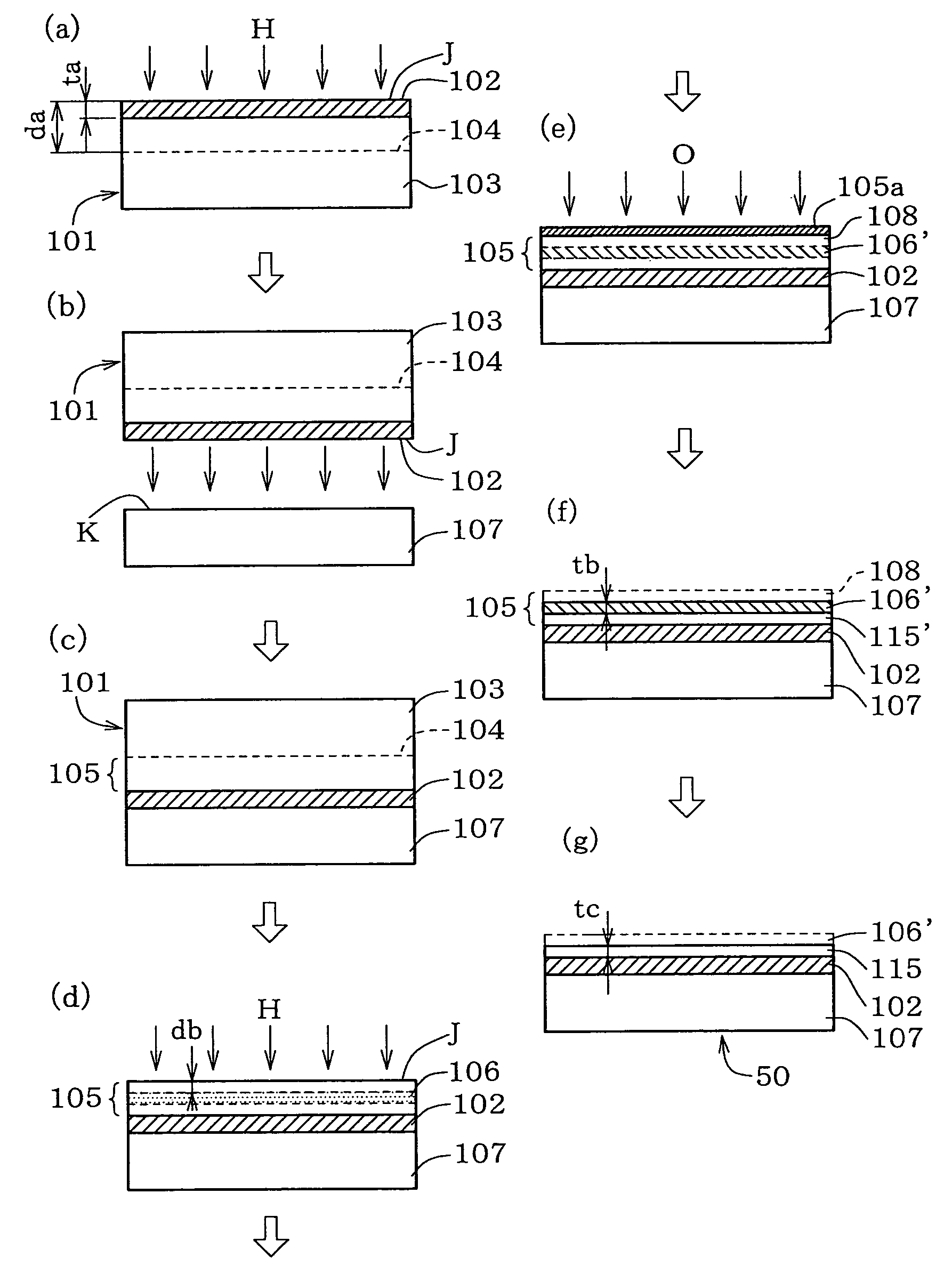
second embodiment

[0063]FIG. 7 explains a basic embodiment of the method of fabricating an SOI wafer according to the second embodiment of this invention. First, a base wafer 107 as a first silicon single crystal substrate shown in process step (b) and a bond wafer 101 as a second silicon single crystal substrate shown in process step (a) are obtained. As shown in process step (a), the bond wafer 101 herein has, formed on a first main surface J side thereof, a silicon oxide film 102 as an insulating film. The silicon oxide film 102 can typically be formed by thermal oxidation such as wet oxidation, where it is of course allowable to adopt other methods such as CVD (Chemical Vapor Deposition). Thickness of the silicon oxide film 102 ta is typically set to 50 nm to 2 μm or around, considering that it is used as an insulating layer typically in MOS-FET or the like.

[0064]Then, as shown in process step (a), the first main surface J of the bond wafer 1, or the main surface J on which the silicon oxide film...


PUM

PropertyMeasurementUnit
temperatureaaaaaaaaaa
thicknessaaaaaaaaaa
thicknessaaaaaaaaaa

Abstract

After completion of annealing for bonding of the base wafer 1 and bond wafer 2, the bond wafer 2 is thinned to a first thickness suitable for ion implantation, and boron is ion-implanted to thereby form a high-boron-concentration layer 10. A second thinning step based on selective etching is then carried out while using the high-boron-concentration layer 10 as an etch stop layer. This is successful in providing a method of fabricating an SOI wafer which is suppressed both in intra-wafer uniformity of the firm thickness and in inter-wafer uniformity of the film thickness even when a required level for the thickness of the SOI layer is extremely small.

Description

TECHNICAL FIELD[0001]This invention relates to a method of fabricating an SOI wafer.BACKGROUND ART[0002]There are general trends in mobile communication such as using cellular phones or the like to handle high-frequency signal of several-hundred-MHz, and this raises needs for semiconductor devices having desirable high-frequency characteristics. For example, semiconductor devices such as CMOS-IC and high-voltage-resistance IC use so-called SOI wafer configured so that a silicon oxide film insulating layer is formed on a silicon single crystal substrate (also referred to as base wafer, hereinafter), and further thereon another silicon single crystal layer is formed by stacking as an SOI (Silicon on Insulator) layer. For the case where this is used for semiconductor devices for high-frequency use, it is necessary to use a high-resistivity silicon single crystal as the base wafer in order to reduce high-frequency loss.[0003]One representative method of fabricating the SOI wafer is know...

Claims


Application Information

Patent Timeline
Patent Type & Authority Patents(United States)
IPC IPC(8): H01L21/30H01L21/762H01L27/12
CPCH01L21/76254
Inventor MITANI, KIYOSHIYOKOKAWA, ISAO
Owner SHIN-ETSU HANDOTAI CO LTD
Why Eureka
Try Eureka