

Ion beam apparatus and sample processing method
a sample processing method and beam apparatus technology, applied in material analysis using wave/particle radiation, instruments, nuclear engineering, etc., can solve the problems of high processing position accuracy, and increased beam spread, and achieve high processing position accuracy and throughput high
- Summary
- Abstract
- Description
- Claims
- Application Information
AI Technical Summary
Benefits of technology
Problems solved by technology
Method used
Image

Examples
embodiment 1
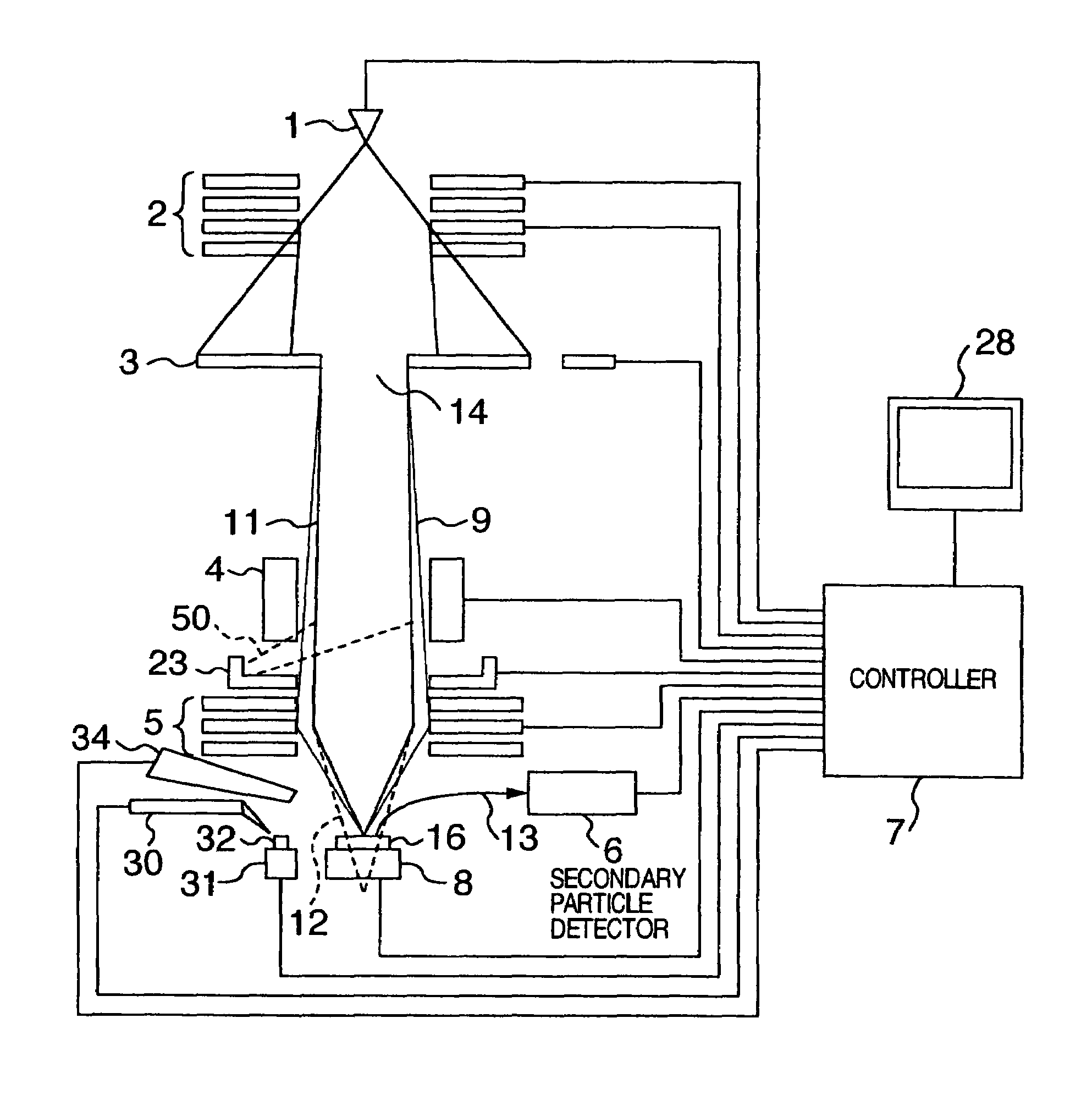
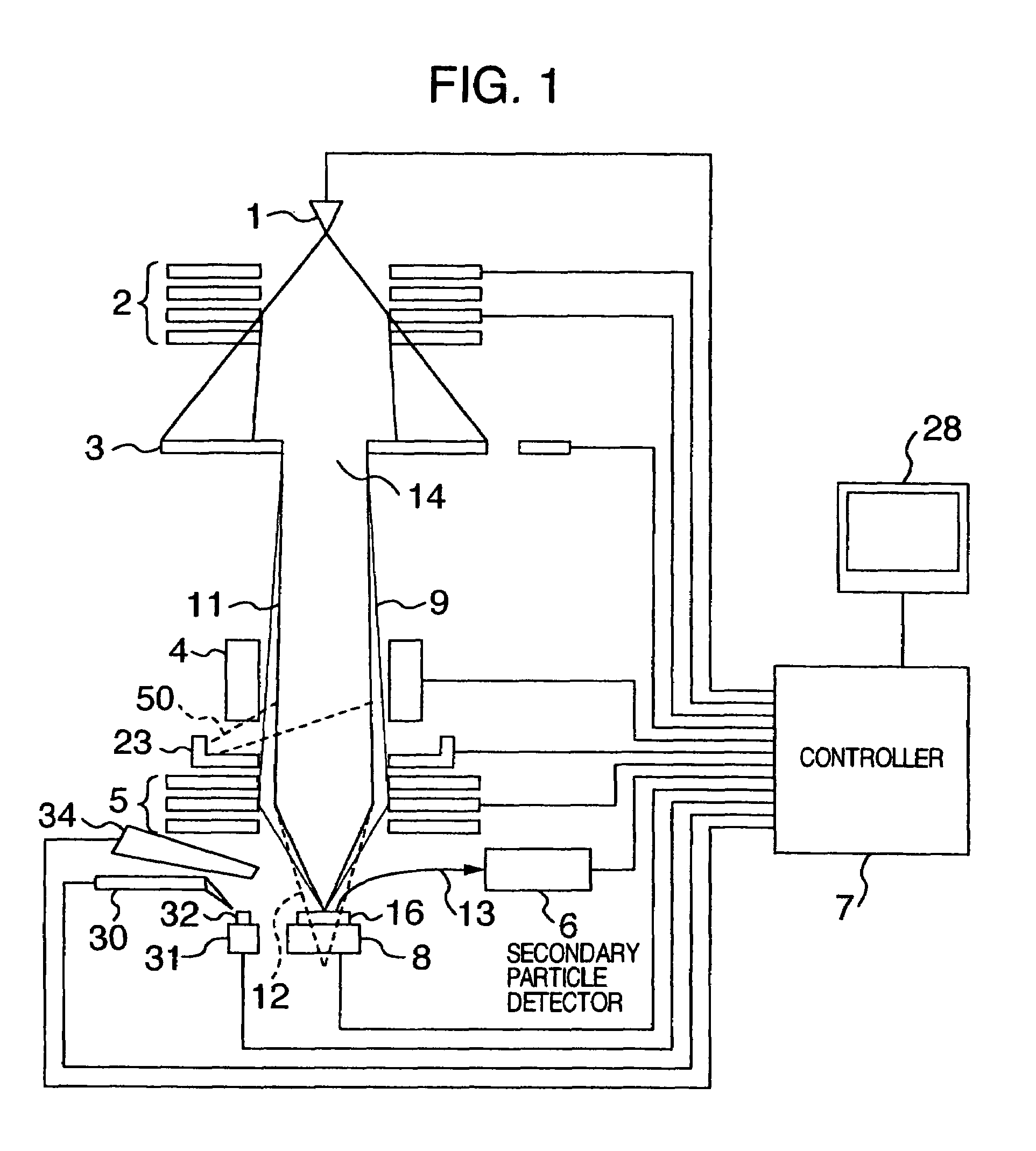
[0058]Referring to first to FIG. 1, an example of an ion beam apparatus according to the invention is schematically illustrated. The ion beam apparatus comprises ion generating means 1 using a gallium liquid metal ion source, focusing means 2 and illuminating means 5 each using a Butler type electrostatic Einzel-lens, a restriction diaphragm 3 having a plurality of apertures of different opening diameters at least one of which uses a variable aperture of opening diameter 14 for permitting the beam current to have a critical value, at which the influence of a skirt spread of beam distribution cannot be negligible in practice, or more, beam deflecting means 4 using a two-stage 8-pole deflector, a specimen stage 8 for carrying a specimen or sample 16, a secondary particle detector 6 using either a scintillator in the case of secondary particles 13 being secondary electrons or a micro-channel plate (abbreviated as MCP) in the case of secondary particles 13 being secondary ions, control ...
embodiment 2
[0099]Referring now to FIGS. 13A and 13B, the construction of another example of the ion beam apparatus according to the invention is schematically illustrated. As schematically shown in FIG. 13A, the apparatus uses a mask 19 in place of the restriction diaphragm 3, and a shaped ion beam (beam for forming an image of opening of the mask on the sample surface) is used as the edge processing ion beam. FIG. 13B shows a top view of an example of the mask 19. This apparatus can be constructed substantially similarly to the apparatus according to the embodiment 1. The mask 19 has openings of desired forms, for example, a rectangular opening 20, an opening 501 constructed of two oblong holes and a circular opening 502, of which at least one is the opening having an area for acquisition of a beam current value (for example, 15 nA or more) at which the influence of the skirt spread in beam distribution cannot be negligible in practice in the ion beam processing.
[0100]In FIG. 13A, only ion be...
embodiment 3
[0104]Referring to FIG. 14, there is illustrated an example of an ion beam apparatus having two ion beam optical systems 70 and 71 each being identical to that in the embodiments 1 and 2. The two ion beam optical systems 70 and 71 are controlled by control means 7. The number of the ion beam optical systems is in no way limited to two but may be three or more. The optical axes of the respective ion beam optical systems are so arranged as to cross each other on one point on the sample 16.
[0105]Advantages of the provision of a plurality of ion beam optical systems can be enumerated as below. With the ion beam optical system arranged in an axial direction oblique to the sample, oblique processing can be conducted without inclining a specimen stage 8 and the specimen stage can dispense with the oblique shaft so as to be simplified in construction. With the two ion beam optical systems provided, two sites can be processed simultaneously to improve the throughput. Further, observation / pro...
PUM
| Property | Measurement | Unit |
|---|---|---|
| beam current | aaaaa | aaaaa |
| beam current | aaaaa | aaaaa |
| beam current | aaaaa | aaaaa |
Abstract
Description
Claims
Application Information