Visible-light-responsive photoactive coating, coated article, and method of making same

Inactive Publication Date: 2006-08-29
PPG IND OHIO INC
View PDF60 Cites 25 Cited by
  • Summary
  • Abstract
  • Description
  • Claims
  • Application Information

AI Technical Summary

Benefits of technology

[0008]Therefore, it would be advantageous to provide a method of making a PA coating with photoabsorption in the visible region that is compatible with a co

Problems solved by technology

This approach can be labor, time, and/or cost intensive.
A problem with these conventional PC coatings is that they typically exhibit photoactivity or photocatalysis only upon exposure to ultraviolet (UV) light in wavelengths shorter than about 380 nanometers (nm).
However, these ion implantation and sol-gel coating methods are not economically or practically compatible with certain application conditions or substrates.
For example, in a conventional float glass process, the float glass ribbon in the molten metal bath can be too hot to accept the sol due to evaporation or chemical reaction of the solvent used in the sol.
Reheating to a temperature s

Method used


Image

  • Visible-light-responsive photoactive coating, coated article, and method of making same
  • Visible-light-responsive photoactive coating, coated article, and method of making same
  • Visible-light-responsive photoactive coating, coated article, and method of making same

Examples


Embodiment Construction

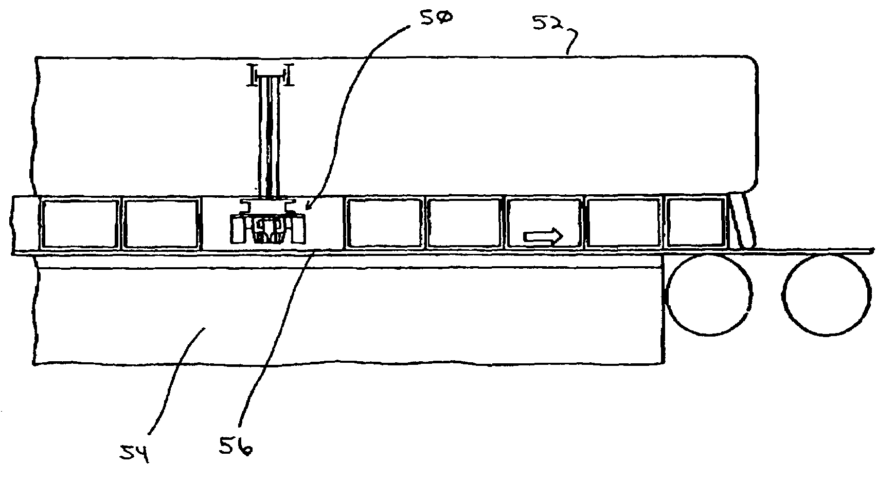
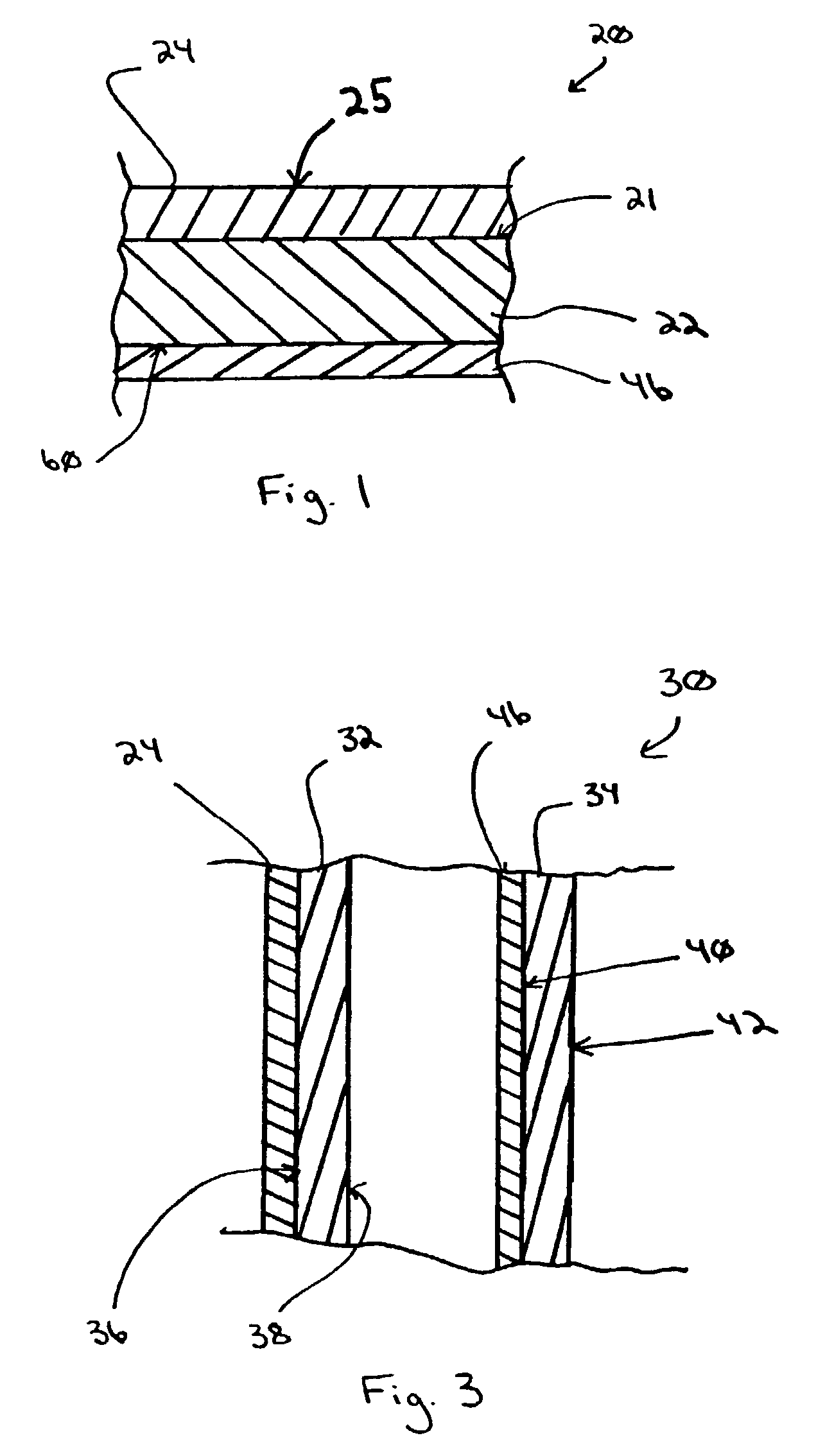
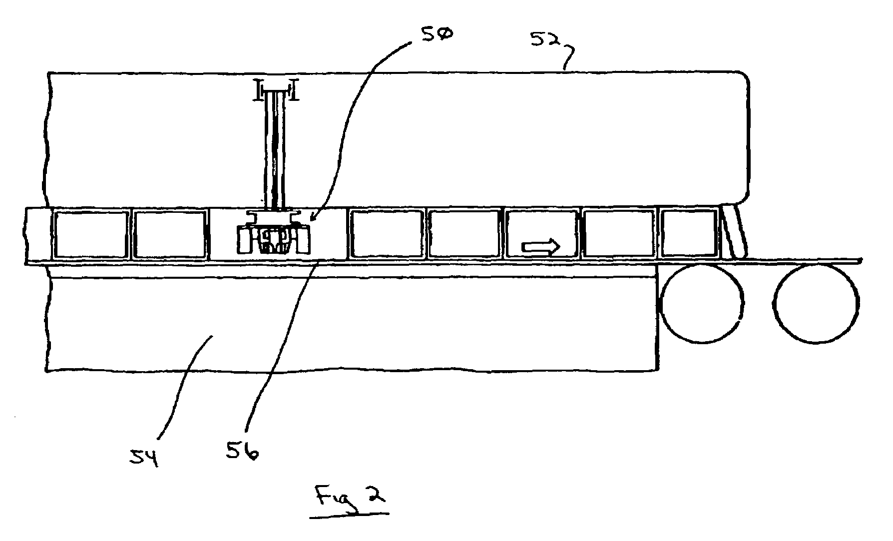
[0016]As used herein, spatial or directional terms, such as “inner”, “outer”, “above”, “below”, “top”, “bottom” , and the like, relate to the invention as it is shown in the drawing figures. However, it is to be understood that the invention can assume various alternative orientations and, accordingly, such terms are not to be considered as limiting. Further, all numbers expressing dimensions, physical characteristics, processing parameters, quantities of ingredients, reaction conditions, and the like used in the specification and claims are to be understood as being modified in all instances by the term “about”. Accordingly, unless indicated to the contrary, the numerical values set forth in the following specification and claims are approximations that can vary depending upon the desired properties sought to be obtained by the present invention. At the very least, and not as an attempt to limit the application of the doctrine of equivalents to the scope of the claims, each numeric...


PUM

PropertyMeasurementUnit
Nanoscale particle sizeaaaaaaaaaa
Temperatureaaaaaaaaaa

Abstract

A method is provided for forming a photoactive coating having a photoabsorption band in the visible region of the electromagnetic spectrum. The method includes depositing a precursor composition over at least a portion of a float glass ribbon in a molten metal bath by a CVD coating device. The precursor composition includes a titania precursor material and at least one other precursor material selected from chromium (Cr), vanadium (V), manganese (Mn), copper (Cu), iron (Fe), magnesium (Mg), scandium (Sc), yttrium (Y), niobium (Nb), molybdenum (Mo), ruthenium (Ru), tungsten (W), silver (Ag), lead (Pb), nickel (Ni), rhenium (Re), and mixtures thereof.

Description

CROSS-REFERENCE TO RELATED APPLICATIONS[0001]This application is a continuation-in-part of U.S. application Ser. No. 10 / 075,316 to Greenberg et al., entitled “Photocatalytically-Activated Self-Cleaning Appliances”, filed Feb. 14, 2002, now U.S. Pat. No. 6,722,159, which is a divisional of U.S. application Ser. No. 09 / 282,943 filed Apr. 1, 1999 (now U.S. Pat. No. 6,413,581), which is a divisional of U.S. application Ser. No. 08 / 899,257, filed Jul. 23, 1997 (now U.S. Pat. No. 6,027,766), which claimed the benefit of U.S. Provisional Application Serial No. 60 / 040,566, filed Mar. 14, 1997, all of which applications are herein incorporated by reference in their entirety. This application also claims the benefit of U.S. Provisional Application Ser. No. 60 / 305,057 filed Jul. 13, 2001, which is herein incorporated by reference in its entirety.FIELD OF THE INVENTION[0002]The present invention relates to methods of depositing photoactive coatings on a substrate (e.g., a glass sheet or a conti...

Claims


Application Information

Patent Timeline
IPC IPC(8): C03B18/02C03C17/00B32B9/00B01J35/02B01J37/02B01J37/34C03B18/14C03C17/245C03C17/25C03C17/34C23C14/48C23C16/40
CPCC23C16/40C03C17/245C03C17/2456C03C17/25C03C17/256C03C17/3417C03C17/3435C03C17/3441C03C2217/212Y10T428/265C03C2217/71C03C2218/112C03C2218/152C03C2218/154C03C2218/155C03C2218/156C03C2218/32C03C2218/365Y02T50/67Y10T428/315C03C2217/24Y10T428/31678Y02T50/60
Inventor GREENBERG, CHARLES B.SZANYI, JANOS
Owner PPG IND OHIO INC
Why Eureka
Try Eureka