Integrated gas supply and leak detection system

a gas supply and leak detection technology, applied in the direction of fluid tightness measurement, instruments, machines/engines, etc., can solve the problems of catastrophic leakage not being detected, small leakage amounts can be hazardous, and many manufacturing systems use hazardous and expensive gases, so as to reduce the risk of catastrophic leakage, reduce the complexity, and reduce the cost

Inactive Publication Date: 2006-09-19
PRAXAIR ST TECH INC
View PDF16 Cites 52 Cited by
  • Summary
  • Abstract
  • Description
  • Claims
  • Application Information

AI Technical Summary

Benefits of technology

[0013]The advantages of the embodiments disclosed herein are significant. Practicing the invention can significantly reduce the cost, complexity, and hazards of supplying process gas to one or more applications. By providing leak detection integrated with gas delivery, gas leaks can be mitigated more quickly, resulting in lower costs and halting potentially hazardous situations before they become serious. By providing pressure-based leak testing, the use of costly gas detectors can be minimized. By providing microprocessor control, operator workload is lessened, updated protocols can be incorporated, and the system can respond rapidly to hazards or changing application conditions. By providing a purge gas, leak testing can be conducted with reduced hazard compared to the process gas. By providing multiple leak tests, false alarms are reduced and sensitivity to true alarms is increased, improving safety and reducing operator desensitization to alarms. By providing redundant system components and verification of system components, safety and reliability is increased. By increasing safety, reliability and reducing false alarms, system downtime is reduced, leading to increased productivity.
[0014]The combination of these advantages is expected to reduced the cost and increase the safety and of employing process gases in manufacturing.

Problems solved by technology

Hazardous and expensive gases are used in many manufacturing systems.
A significant problem is delivering these gases to applications in a manufacturing environment while detecting and mitigating leaks.
Even small amounts of leakage can be hazardous, for example, the explosive limit for hydrogen gas at standard temperature and pressure is about 4% by volume.
There are a number of commercially available gas detectors that can be configured for a variety of gases, but they are costly, particularly if contemplated for use with a gas supply system that is spread over a large area.
Also, these detectors provide leak detection only after a detectable amount of gas has leaked and contacted the detector, which can be a significant amount of gas depending on the location of the detector and surrounding air currents.
Furthermore, a catastrophic leak may not be detected until a significant amount of gas has been released, for example, if a high-pressure gas delivery line is accidentally severed.
In a large system, this can create a safety hazard and waste a significant amount of gas before detection.
In response, the sensitivity of the detector can be increased, however, this leads to an increased number of false alarms, which can cause costly downtime and desensitize personnel to real alarms.
However, the system only detects a leak after a significant amount of flammable hydrogen gas has already leaked from the system.
The system is controlled by a hard-wired relay control system and cannot be easily reconfigured for different process conditions or improved safety protocols.
Additionally, the system does not provide redundancy for safety in case of failure of critical components, nor does it provide for automatic calibration and monitoring of critical sensor components.

Method used


Image

  • Integrated gas supply and leak detection system
  • Integrated gas supply and leak detection system
  • Integrated gas supply and leak detection system

Examples


Embodiment Construction

[0026]The foregoing and other objects, features and advantages of the invention will be apparent from the following more particular description of preferred embodiments of the invention, as illustrated in the accompanying drawings in which like reference characters refer to the same parts throughout the different views. The drawings are not necessarily to scale, emphasis instead being placed upon illustrating the principles of the invention.

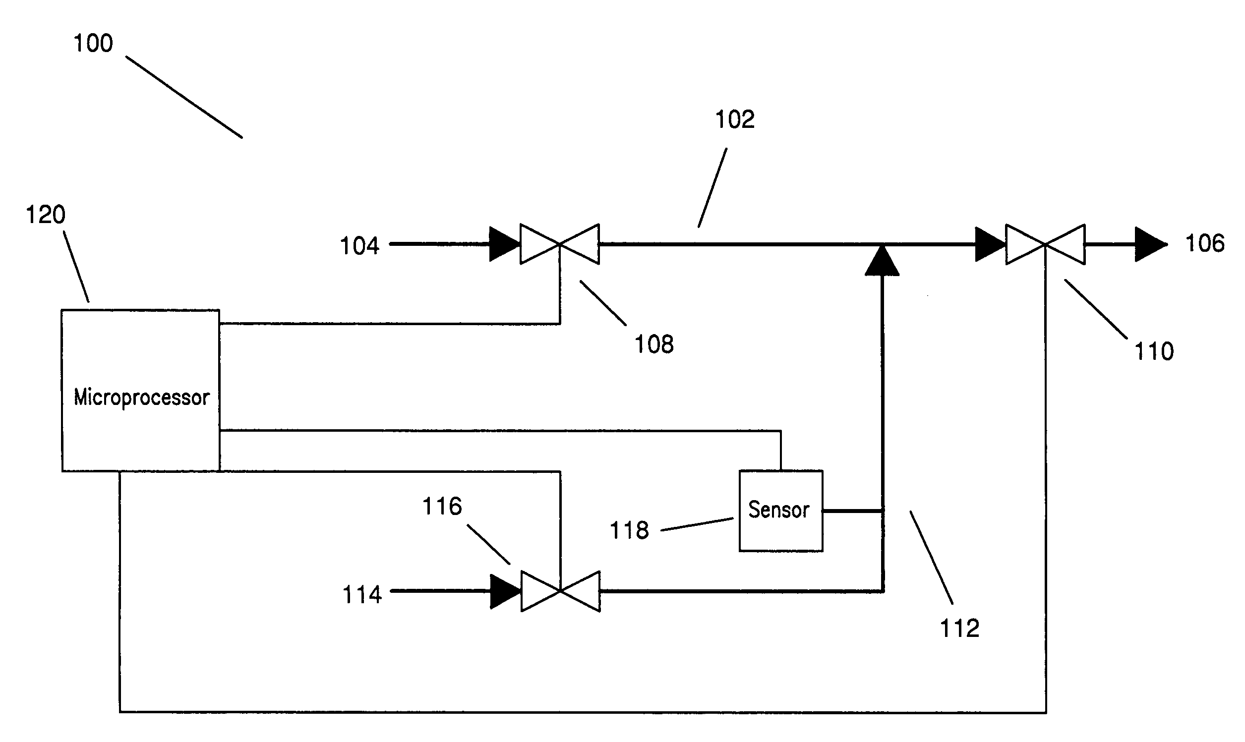
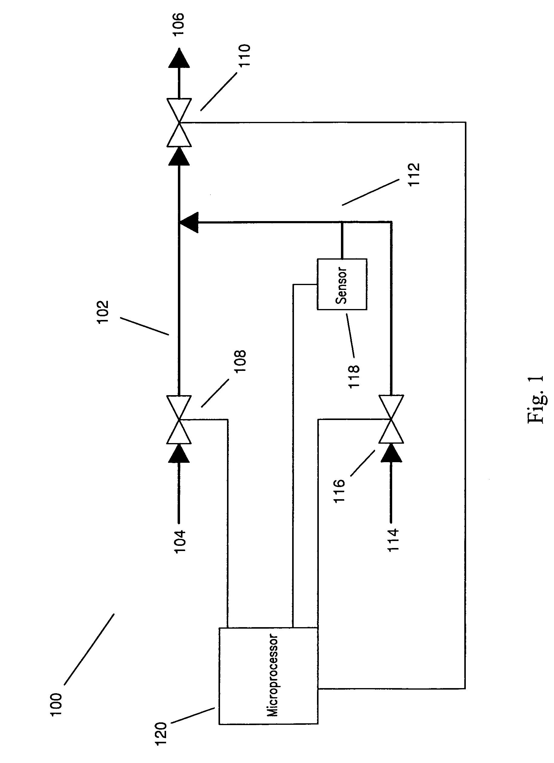
[0027]The invention generally relates to an apparatus and system for integrated gas delivery and leak detection to one or more applications. In particular, the invention is a method an apparatus for delivering a process gas, e.g., H2, and a purge gas, e.g., He, to multiple applications, while integrating multiple methods of leak detection. The present invention is illustrated by the following examples, which are not intended to be limiting in any way.

[0028]FIG. 1 is a schematic of one embodiment of the present invention, system 100, which can als...


PUM


Abstract

The invention generally relates to a system and method for integrated gas delivery and leak detection to one or more applications. The system includes at least one application site, a process conduit extending from a process gas source site to the application site, a first and second process flow control at the process conduit, and a first pressure sensor.
Also included in the system is a microprocessor that is in electronic communication with the flow controls and the first pressure sensor, wherein the microprocessor is programmed to respond to an application standby request by performing a pressure decay test, including closing the second process flow control and pressurizing a portion of the system by opening the first process flow control. Further included in the pressure test is closing the first process flow control when the pressure at the first pressure sensor is at a minimum pressure, and comparing an empirical pressure decay rate at the first pressure sensor with a maximum pressure decay rate, whereby an empirical pressure decay rate that exceeds the maximum pressure decay rate indicates the presence of a leak.

Description

BACKGROUND OF THE INVENTION[0001]Hazardous and expensive gases are used in many manufacturing systems. For example, gases such as hydrogen, helium, oxygen, fluorine, nitrogen, carbon monoxide, nitrous oxide, hydrogen fluoride, arsenic hexafluoride, and the like are used as process gases in a variety of manufacturing situations, for example, etching or chemical vapor deposition in semiconductor processing, gas metal arc welding, chemical manufacturing, petroleum refining, thermal spray coating, and the like. A significant problem is delivering these gases to applications in a manufacturing environment while detecting and mitigating leaks. Even small amounts of leakage can be hazardous, for example, the explosive limit for hydrogen gas at standard temperature and pressure is about 4% by volume.[0002]There are a number of commercially available gas detectors that can be configured for a variety of gases, but they are costly, particularly if contemplated for use with a gas supply system...

Claims


Application Information

Patent Timeline
Patent Type & Authority Patents(United States)
IPC IPC(8): G01M3/04F17D5/06G01M3/28
CPCG01M3/2815F17D5/06
Inventor NUNNALLY, DAVID W.GIFFORD, DOUGLAS J.
Owner PRAXAIR ST TECH INC
Why Eureka
Try Eureka