

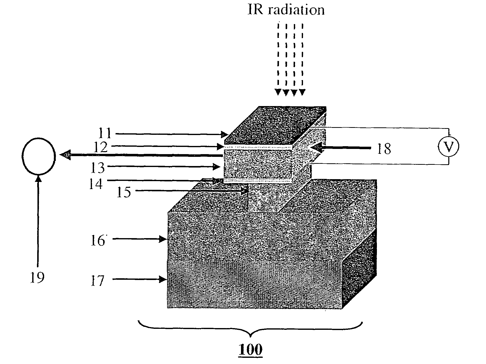
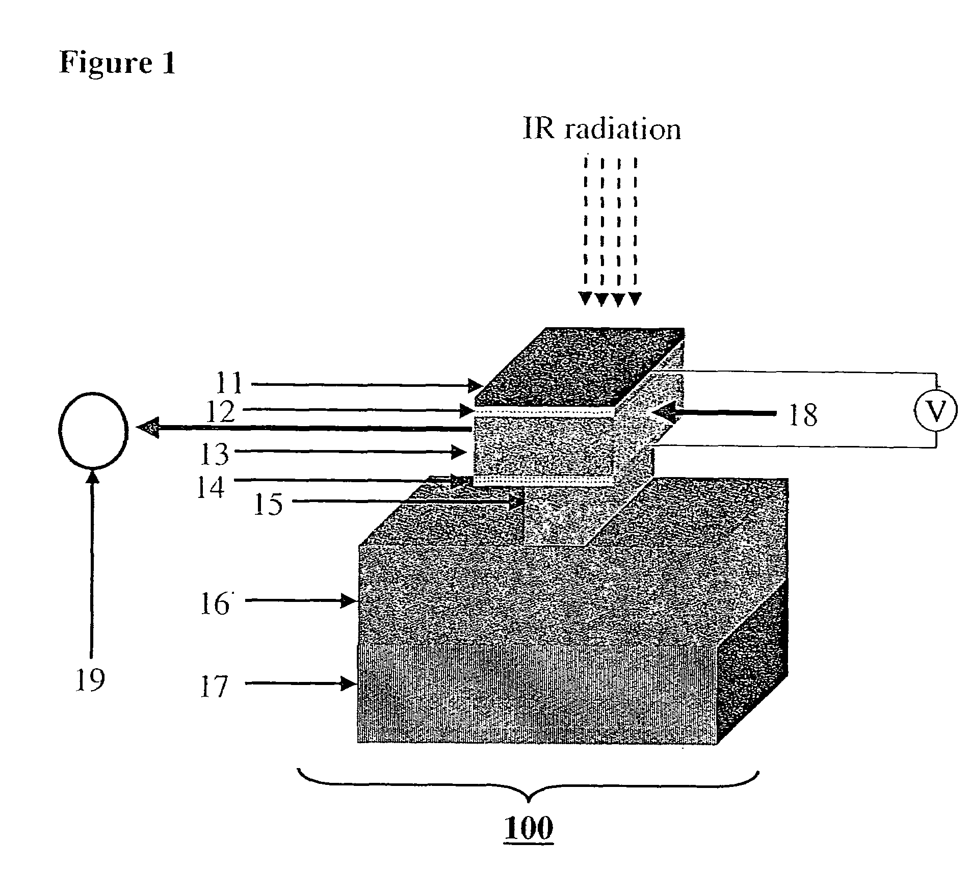
Thermal imaging system and method
a technology of thermal imaging and thermal imaging, applied in the field of remote sensing of heat, can solve the problems of difficult measurement of change in resistivity, unsuitable long distance measuring and imaging, and high heat exchange resistance of tes with its environment, and achieve the effect of reducing nois
- Summary
- Abstract
- Description
- Claims
- Application Information
AI Technical Summary
Benefits of technology
Problems solved by technology
Method used
Image

Examples
embodiment 1
[0045]Embodiment 1 utilizes the crossed-polarizers configuration for a single detector, which is made of a paraelectric material as the EO ingredient. There are several paraelectric EO materials, such as LiTaO3, KTaO3, KTa1-yNbyO3 (known as KTN), K1-xLixTa1-yNbyO3 (KLTN), K1-xNaxTa1-yNbyO3 (KNTN), this list being by no means complete.
[0046]Paraelectric materials are defined by the absence of spontaneous electrical polarization. Since the EO effect relates to the electrical polarization, it therefore follows that any changes in the index of refraction induced by the EO effect will be a function of the product of the applied electric field and the material's dielectric constant. In the mathematical analysis below we limit ourselves to the case where the paraelectric material is also centro-symmetric, in which case the EO effect is quadratic with respect to the applied field. It should be noted, however, that similar equations can be developed also for the linear EO, as indeed for any ...
embodiment 2
[0064]Embodiment 2 is in principle similar to Embodiment 1, with the addition of an extra dummy, which is placed in parallel to the detector (a “parallel dummy”). The role of the parallel dummy is to extract a reference readout signal, which will be subsequently used to null any contribution that is not associated with the IR radiation induced temperature increase. In a preferred embodiment, the parallel dummy is identical to the detector in all parameters, with the exception of the IR absorbing layer. The parallel dummy is placed near the detector, so that both are supported by the same temperature controller.
[0065]FIG. 5 shows schematically the mode of operation of embodiment 2. A laser beam 51 is split to two equi-intensity beams 52 and 53 using a beam splitter (not shown). Alternatively, we can use two different laser beams, of preferably equal intensity and identical state of polarization. However, the usage of two different lasers is likely to enhance the noise, since their fl...
embodiment 3
[0069]Embodiment 3 is another example for a single detector, this time utilizing the MZI configuration. A schematic description of this configuration is given in FIG. 6. A laser beam 61 is split to two equi-intensity beams, a reading beam 62 that passes through a detector 64 and a reference beam 63 that passes through a parallel dummy 65. A phase matching device 66 is added to one of the paths. In the case shown in FIG. 6, device 66 is added in the path of reference beam 63 without loss of generality. As explained in Embodiment 1 above, device 66 may be passive (i.e., of fixed properties), or active (i.e., made of an EO material whose degree of birefringence is controlled by an electric field). The beams are then brought together to interfere at a power meter 67. In the absence of IR radiation, the phase of the two beams should be identical (since the optical length they pass is identical), and therefore a constructive interference should be formed. The phase matching device is then...
PUM
| Property | Measurement | Unit |
|---|---|---|
| thick | aaaaa | aaaaa |
| depth | aaaaa | aaaaa |
| depth | aaaaa | aaaaa |
Abstract
Description
Claims
Application Information