Hologram recording sheet, holographic optical element using said sheet, and its production process

a technology of optical elements and recording sheets, applied in the field of hologram recording sheets, can solve the problems of inferior image quality such as ghost images, impose considerable limitations on the hologram recording material to be used, and achieve the effect of good quality

Inactive Publication Date: 2006-11-07
DAI NIPPON PRINTING CO LTD
View PDF22 Cites 98 Cited by
  • Summary
  • Abstract
  • Description
  • Claims
  • Application Information

AI Technical Summary

Benefits of technology

[0018]An object of the invention is to provide a hologram recording sheet which enables an image of good quality to be obtained and, at the same time, hologram recording to be easily made at an advantageous cost.
[0020]A further object of the invention is to provide a hologram recording sheet which enables an image of good quality to be displayed in multicolor.
[0021]A still further object of the invention is to provide a hologram combiner or display hologram which enables an image of good quality to be displayed in multicolor.
[0022]A still further object of the invention is to provide a heat-wave reflecting film which can reflect heat wave wavelengths in a wide wavelength region and can prevent any reduction in the transmission of visible light, and a method for producing it.
[0023]A still further object of the invention is to provide a holographic filter which can easily achieve a broad band of filter characteristics, and a method for producing it.
[0030]Still further, the invention is characterized by providing a heat-wave reflecting film in which diffraction gratings reflecting heat waves in different wavelength regions are formed on a surface in mosaic configuration, thereby enabling a wide wavelength range of heat waves to be reflected.

Problems solved by technology

However, not only does this give rise to technical difficulties but also imposes some considerable limitation on the hologram recording material to be used.
In addition, this is responsible for inferior image quality such as ghost images.
However, high coating technologies such as slide coating, slot coating and curtain coating are needed for the uniform lamination of many hologram sensitive materials with their interfaces kept constant, and much time is taken to predetermine the required conditions, etc.
At the same time, this approach has a cost problem, because there is need of using an exclusive fountain head.
However, a grave problem with this is that the unrestricted migration of the monomer takes place through the interfaces; in other words, the pitch of the interference fringes cannot be obtained, as designed, although depending on what type of hologram-recording process is used.
Not only does this give rise to technical difficulties, but also places some considerable limitation on the hologram recording material to be used, because the sensitive material is required to be sensitive to plural colors.
Moreover, this is responsible for inferior image quality such as large noises, for instance, ghost images.
However, conventional heat-wave reflecting films such as deposited films, except holograms, when used to reflect heat waves in a wide wavelength range, result unavoidably in a lowering of the transmission of visible light, because they are likely to reflect or absorb visible light.
Diffraction gratings, although they may somehow be used as heat-wave reflecting films, will make it difficult to reflect heat waves in a wide wavelength range due to their wavelength selectivity.
However, a problem with this superposition is that the light diffracted by one layer is further diffracted by another layer, thus making it very difficult to achieve any effective reflection of heat waves.
However, it is extremely difficult to produce a wide band width of fiter such as a solar reflector with the use of a diffracting grating with interference fringes recorded thereon.
In particular, a grave problem with widening band width by conventional material treatments is that it is extremely difficult to regulate the reflection wavelength region to a specific region.
However, this volume hologram has a narrow diffraction wavelength range; no volume hologram having a wide wavelength range is available as yet.

Method used


Image

  • Hologram recording sheet, holographic optical element using said sheet, and its production process
  • Hologram recording sheet, holographic optical element using said sheet, and its production process
  • Hologram recording sheet, holographic optical element using said sheet, and its production process

Examples


example 1

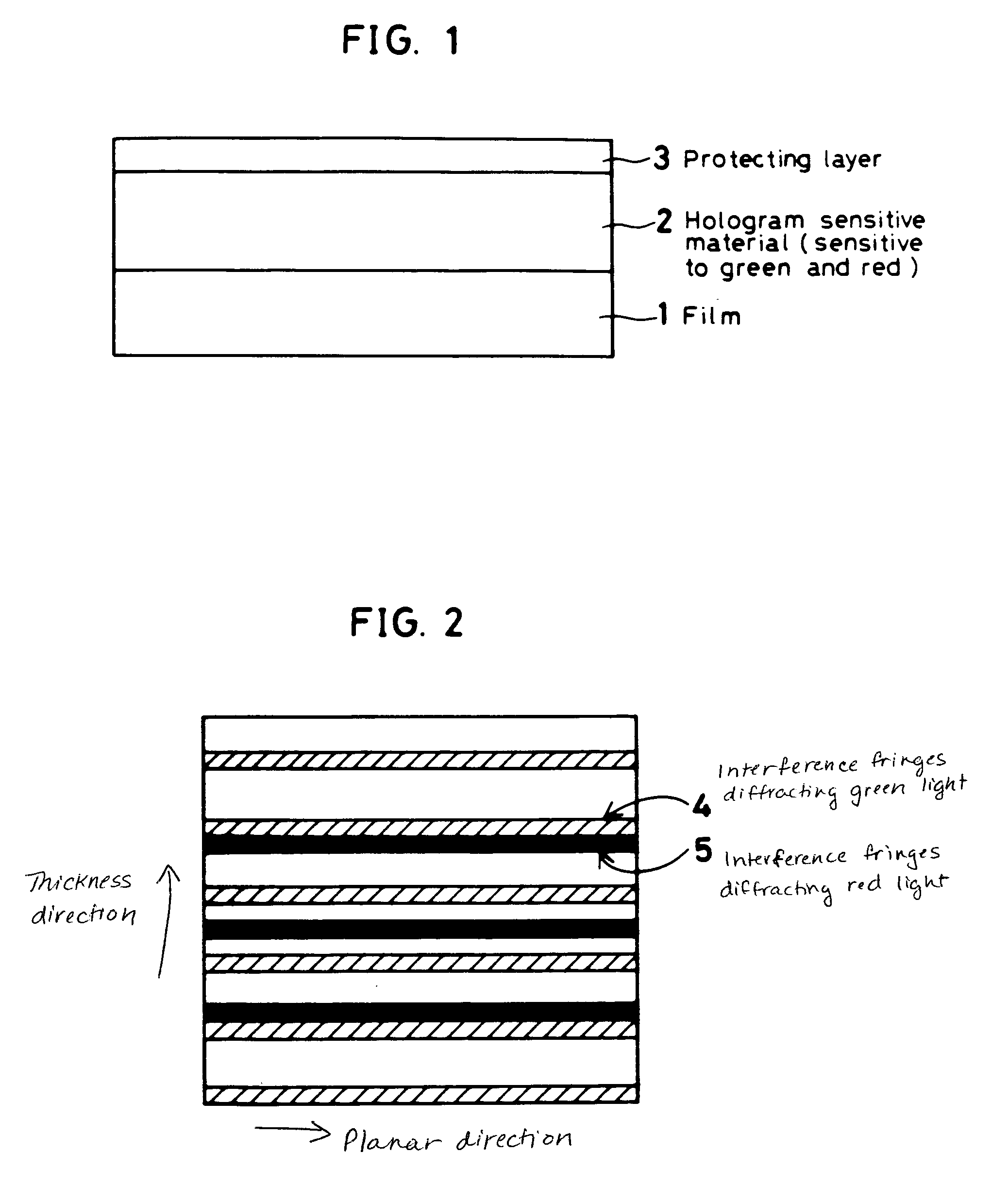
[0087]For a solution sensitive to green light, 50 parts of polyvinylcarbazole, 40 parts of tribromophenoxyethyl methacrylate, 1 part of cyanine dye (NK-1420 made by Nippon Kanko Shikiso Co., Ltd.), 5 parts of 3,3′,4,4′-tetra(t-butylperoxycarbonyl)benzophenone, and 5 parts of a nonylphenyl alcohol / ethylene oxide adduct (Emulgen 903 made by Kao Soap Co., Ltd.) were dissolved in methyl ethyl ketone. For a solution sensitive to red light, 50 parts of polyvinylcarbazole, 40 parts of tribromophenoxyethyl methacrylate, 1 part of squarylium dye (NK-3024 made by Nippon Kanko Shikiso Co., Ltd.), 5 parts of 3,3′,4,4′-tetra(t-butylperoxycarbonyl)benzophenone, and 5 parts of a nonylphenyl alcohol / ethylene oxide adduct (Emulgen 903 made by Kao Soap Co., Ltd.) were similarly dissolved in methyl ethyl ketone. These solutions were printed on a 50 μm PET film (HP-7 made by Teijin Limited) by screen printing using a 150-mesh screen printing plate and then dried to form 10 cm·10 cm green-light sensitiv...

example 2

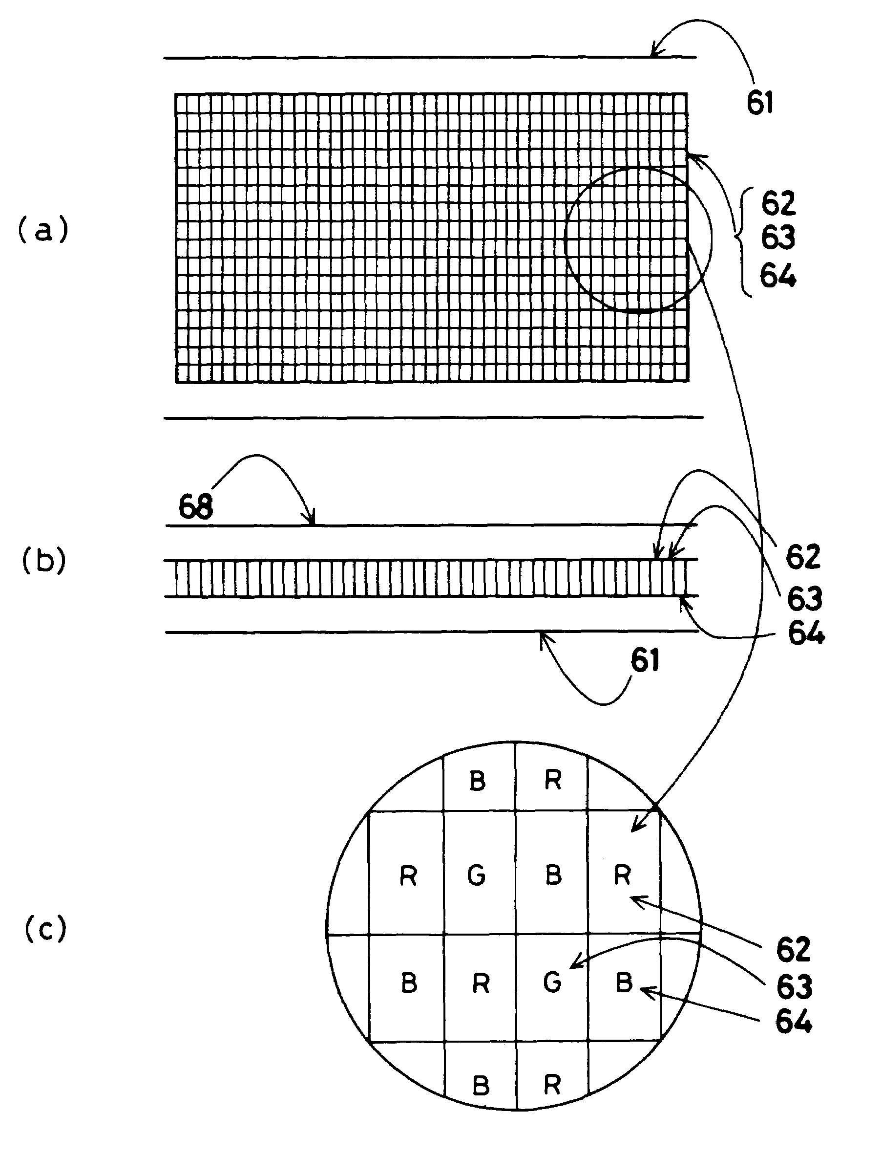
[0089]Methyl ethyl ketone solutions of the same photosensitive solutions as in Example 1 were printed on a 50 μm PET film (HP-7 made by Teijin Limited) by die coating using a slot orifice having different discharge ports of 25 cm and 5 cm, and then dried to form the green- and red-light sensitive materials, each having a thickness of 20 μm, according to the striped pattern shown in FIG. 8(b). This sheet was further laminated thereon with a PET film (Lumilar T60 made by Toray Industries, Inc.) and then rolled up.

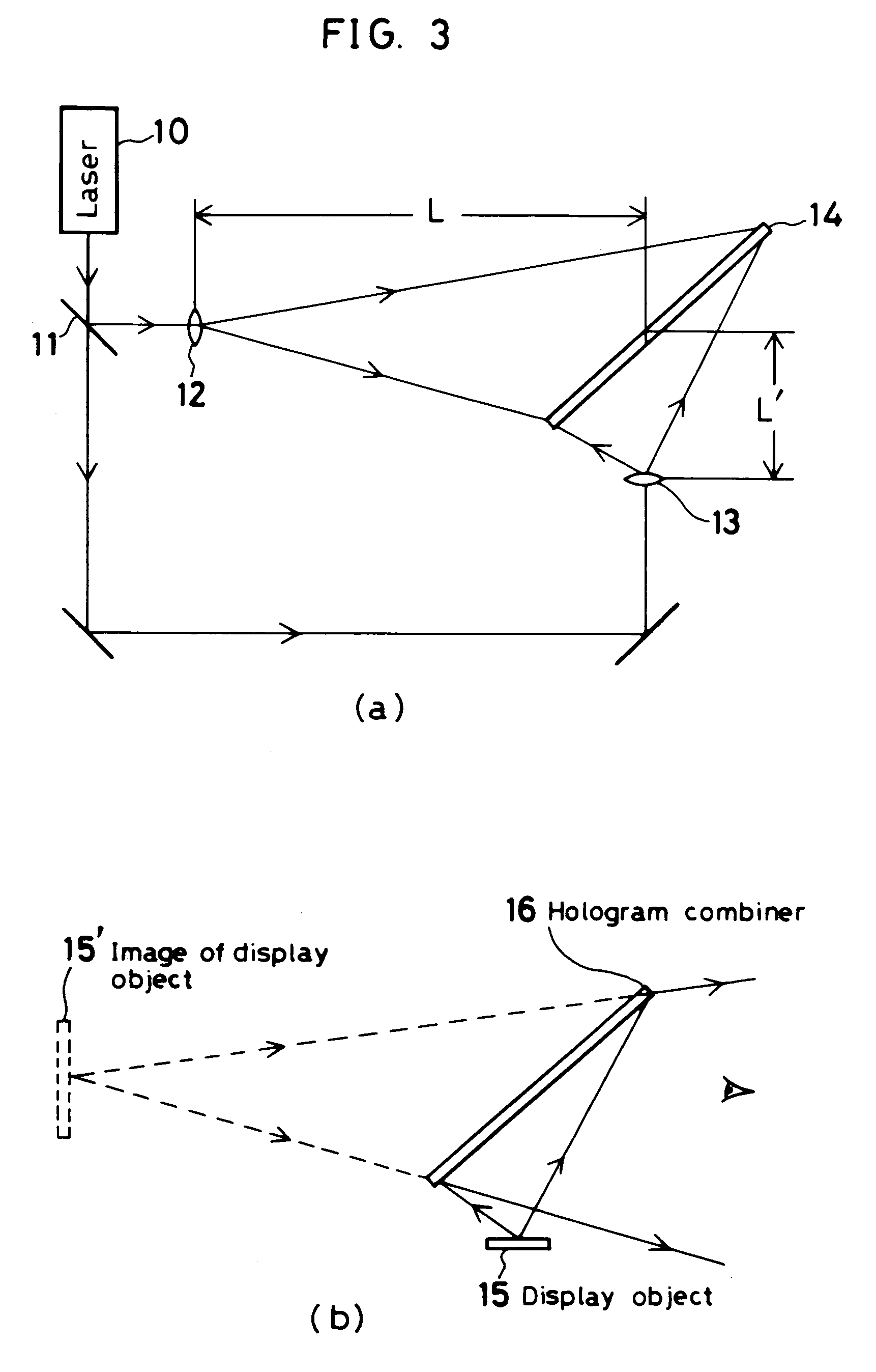
[0090]Using 514 nm argon laser light and 647 nm krypton laser light as light sources, a head-up display combiner was produced on this hologram sensitive material by the sequential exposure technique. Consequently, a satisfactory speed-indicating projection chart was obtained, which included the speed indicator 46 projected in green color in the green-light diffracting zone 44 and the emergency warning light 47 projected in red color in the red-light diffracting zone 45, as sh...

example 3

[0098]The same green- and red-light sensitive solutions as in Example 1 were dissolved in methyl ethyl ketone at a solid content of. 20 wt %. The resulting solution for green light was coated on a 50 μm PET film (HP-7 made by Teijin Limited) at a dry coverage of 25 μm by gravure coating using a gravure roll. Laminated on this layer was a 25 μm PET film (HP-7 made by Teijin Limited) treated on both it sides, on which the sensitive solution for red light was further coated at a dry coverage of 25 μm by gravure coating using a gravure roll. This sheet was laminated thereon with an additional PET film (Lumilar T60 made by Toray Industries, Inc.) and then rolled up.

[0099]Using 514 nm argon laser light and 647 nm krypton laser light as light sources, a head-up display combiner was produced on this hologram sensitive medium. Consequently, such a satisfactory speed-indicating projection chart as shown in FIG. 14 was obtained.


PUM


Abstract

The hologram recording sheet according to the invention is made up of a base film and hologram sensitive materials sensitive to different wavelength regions formed therein in a desired pattern, or a film and at least two hologram recording sensitive materials sensitive to different wavelength regions laminated on the film with a transparent plastic spacer layer located therebetween, thereby enabling the required diffraction light wavelengths to be recorded on the required sites without producing unnecessary interference fringes. At least two hologram recording sensitive materials sensitive to different wavelength regions are formed on different sites on a film in dotted or striped configuration, the size of which is up to 200 mm or at least twice as large as the thickness of the sensitive material layers, thereby enabling regions diffracting light of different wavelengths to be formed in the form of independent sets of interference fringes.

Description

BACKGROUND OF THE INVENTION[0001]The present invention relates to a hologram recording sheet suitable for multicolor displays which is required to selectively diffract light of two or more wavelengths, to a holographic optical element such as a multicolor head-up display combiner, a multicolor display hologram, a heat-wave reflecting film that is effectively used on the windows of a car or building, a broad band of holographic filter, and a diffraction grating which, like the heat-wave reflecting film, diffracts light in a wide wavelength range, and to a process for producing such a holographic optical element.[0002]So far, hologram sensitive materials have been widely used for holograms for ornamental, forgery-preventing, optical element or other purposes. Usually, a typical hologram sensitive material is made up of a PET substrate on which a hologram sensitive material 2 sensitive to green and red light is uniformly coated in the form of a single layer, as can be seen from FIG. 1....

Claims


Application Information

Patent Timeline
Patent Type & Authority Patents(United States)
IPC IPC(8): G03H1/02G03H1/18G03H1/24
CPCG03H1/02G03H1/0236G03H1/18G03H1/24G03H1/26G02B5/32G03H2001/0439G03H2001/186G03H2001/2263G03H2001/2271G03H2001/263G03H2001/266G03H2001/303G03H2222/16G03H2223/18G03H2230/10G03H2250/34G03H2250/44G03H2260/12G03H2270/23
Inventor UEDA, KENJIHOTTA, TSUYOSHITANIGUCHI, YUKIOSEKIGUCHI, ATSUSHIIRIYAMA, HIDEYUKI
Owner DAI NIPPON PRINTING CO LTD
Why Eureka
Try Eureka