

System and method for detecting water vapor within natural gas
- Summary
- Abstract
- Description
- Claims
- Application Information
AI Technical Summary
Benefits of technology
Problems solved by technology
Method used
Image

Examples
Embodiment Construction
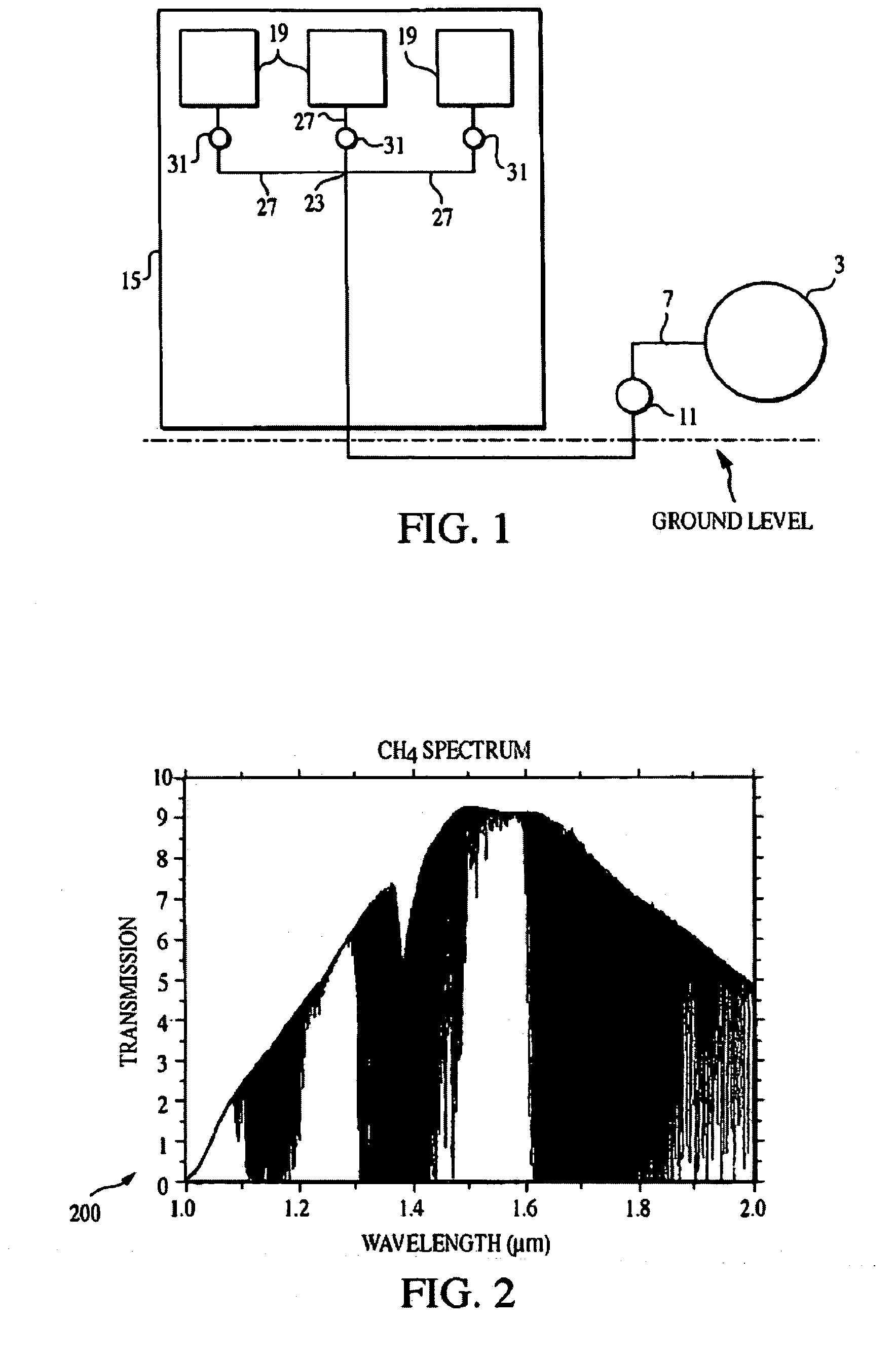
[0025]The current system and method relate to the measurement of moisture content in natural gas based on absorption of light at specific wavelengths where water molecules absorbs light strongly. Generally, this technique is referred to as absorption spectroscopy, and is applicable to the measurement of a wide range of gases, liquids, and solids.
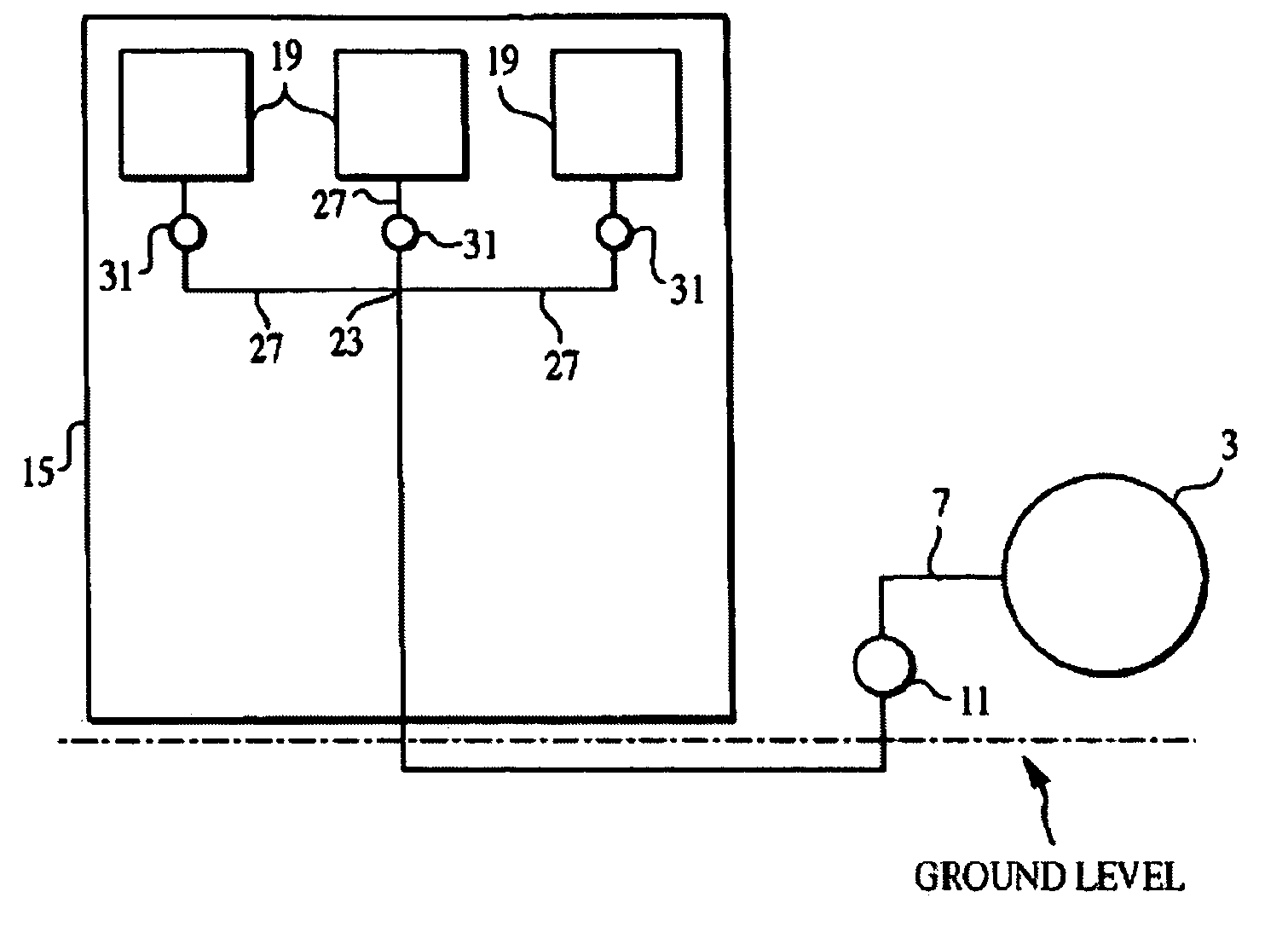
[0026]As seen in FIG. 1, a pipeline 3 of natural gas is coupled to a gas line 7 which includes a regulator 11 for reducing the gas pressure within the gas line. From the regulator, the gas line enters a sampling shelter 15 that houses a plurality of sensors 19 (with at least one being an optical gas sensor as the present invention may be utilized in parallel with the chemical sensors described above). If multiple sensors are employed, they are connected in parallel to the gas line so that gas flow can be simultaneously directed to all of the sensors. This is accomplished after the gas line enters the sampling shelter by diverting gas into a ...
PUM
 Abstract
Description
Claims
Application Information