
Reactor for solar processing of slightly-absorbing or transparent gases

a solar energy and gas processing technology, applied in the direction of machines/engines, combustible gas production, energy input, etc., to achieve the effect of preventing re-associating back-reactions, reducing back-radiation losses, and high intensity and high temperatures

Inactive Publication Date: 2006-11-28
SUNDROP FUELS
View PDF4 Cites 63 Cited by
  • Summary
  • Abstract
  • Description
  • Claims
  • Application Information

AI Technical Summary

Benefits of technology

[0011]A primary advantage of the present invention is that it provides secondary focusing of solar energy to realize the high intensity and high temperatures needed for disassociation processes, along with the necessary rapid cooling or quenching to prevent re-associating back-reactions.
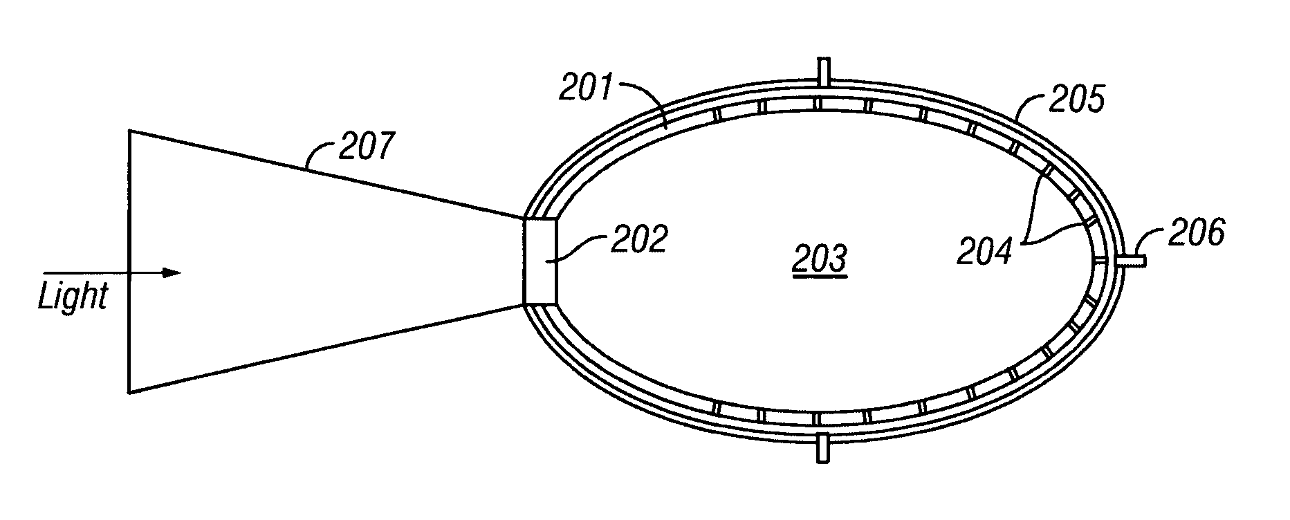
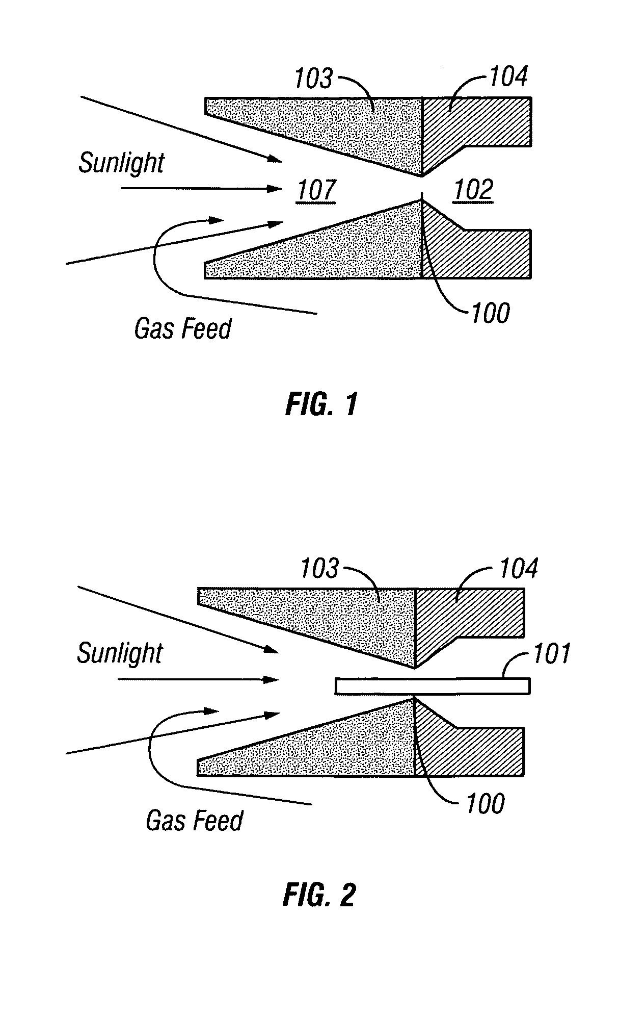
[0012]There is provided according to the invention a solar powered endothermic reactor apparatus for processing slightly-absorbing or transparent gases, the apparatus comprising: a reaction zone through which passes the process gas; means for concentrating incoming solar radiation in the reaction zone; and means for limiting back-radiation losses from the reaction 10 zone by controlling direct reflection and thermal re-radiation. The means for concentrating comprises a highly reflective funnel, the funnel comprising: a longitudinal axis; a mouth for the admission of solar energy; a wall having an optically smooth inner surface and defining a radial cross-sectional area of the funnel, wherein the cross-sectional area monotonically decreases along the axis from the mouth toward the reaction zone. The funnel wall defines a cone of revolution around the axis, or, alternatively, a paraboloid of revolution around the axis. The optically smooth inner surface preferably comprises highly reflective metal. The means for limiting back-radiation losses comprises means for limiting a high-temperature area of the reaction zone. The means for limiting preferably comprises a hot ceramic rod in a zone of highest irradiance along the axis. The apparatus preferably further comprising means for actively cooling the funnel wall. The means for limiting back-radiation losses preferably comprises a holraum reactor chamber disposed downstream from the reaction zone, the holraum reactor chamber comprising: an intake aperture for admitting process gas; and black walls; wherein the ratio of the area of the intake aperture to the area of the walls is less than approximately 0.5, and the holraum reactor chamber exhibits limited radiation loss due to the ratio. The means for concentrating comprises a highly reflective funnel collector, and the means for eliminating back-radiation losses comprises a holraum reactor chamber, the holraum reactor chamber comprising an intake aperture for admitting process gas; and black walls; wherein the ratio of the area of the intake aperture to the area of the walls is less than approximately 0.5, and wherein the funnel collector facilitates gathering sunlight through the intake aperture in to achieve the area ratio. The apparatus preferably further comprises a large-area cool surface downstream the reaction zone, wherein the ratio of cooling surface to gas flow area is at least 5.0. The apparatus alternatively further comprises a multi-funnel plate and a matching cooling plate. The multi-funnel plate defines a highly reflecting metal portion and a rearward ceramic throat portion. Such an embodiment of the apparatus may further comprise a radiation shield disposed between the hot multi-funnel plate and the matching cooling plate, and may also include means for injecting cool fluid into the process gas immediately downstream from the reaction zone.
[0013]There also is provided a method for solar powered processing of a slightly-absorbing or transparent gas, comprising the steps of passing the gas through a reaction zone; concentrating incoming solar radiation in the reaction zone; and injecting cool fluid into the process gas immediately downstream from the reaction zone to arrest a back-reaction. The step of arresting a back-reaction may comprise arresting the reactions: CO+O+M→CO2+M and CO+O2→CO2+O. The method may comprise the additional step gathering heat from a reactor structure to suppress re-radiation and to drive a heat engine. The step of gathering comprises gathering heat from a cooling mechanism that arrests the back reaction by cooling the gas to a cool temperature. The back reactions to be arrested by the method include: CO+O+M→CO2+M and CO+O2→CO2+O; and the cool temperature to be achieved is less than approximately 800 C.
[0014]There also is disclosed a method for solar powered processing of a gas that absorbs only infrared light, the method comprising: directing solar energy, in the form of light rays, into a holraum reactor chamber; admitting the gas into a holraum reactor chamber; allowing the light rays to repeatedly strike interior walls of the holraum reactor chamber; and re-thermalizing the solar energy, thereby restoring the portion of the solar spectral energy that is absorbed by the gas.
[0015]Other objects, advantages and novel features, and further scope of applicability of the present invention will be set forth in part in the detailed description to follow, taken in conjunction with the accompanying drawings, and in part will become apparent to those skilled in the art upon examination of the following, or may be learned by practice of the invention.
[0016]The objects and advantages of the invention may be realized and attained by means of the instrumentalities and combinations particularly pointed out in the appended claims.

Problems solved by technology

The very large-scale combustion of these fuels causes a number of environmental concerns, including accumulation of carbon dioxide (CO2) in the Earth's atmosphere.

Method used


Image

  • Reactor for solar processing of slightly-absorbing or transparent gases
  • Reactor for solar processing of slightly-absorbing or transparent gases
  • Reactor for solar processing of slightly-absorbing or transparent gases

Examples


second embodiment

[0041]In a second embodiment, illustrated FIG. 2, a hot central rod funnel reactor, a rod 101 is cantilevered through the reactor, extending along its centerline axis partway upstream and downstream of the throat 100. This alternative embodiment otherwise is substantially similar to the embodiment of FIG. 1 as to form and function. The rod 101 serves to preheat the passing gas. Rod 101 becomes extremely hot due to the intense sunlight energy directed to the centerline axis of the funnel 103. The rod 101 is fashioned from a very high temperature material, such as a ceramic. The rod 101 provides surface area for contact heating, and is also much hotter than the walls of the funnel 103 because of its position on the axis and its absorption properties. Significant molecular dissociation occurs along and in the immediate vicinity of the hot rod 101 because it preheats the gas and also is disposed in the location of greatest solar irradiation for direct photolysis.

third embodiment

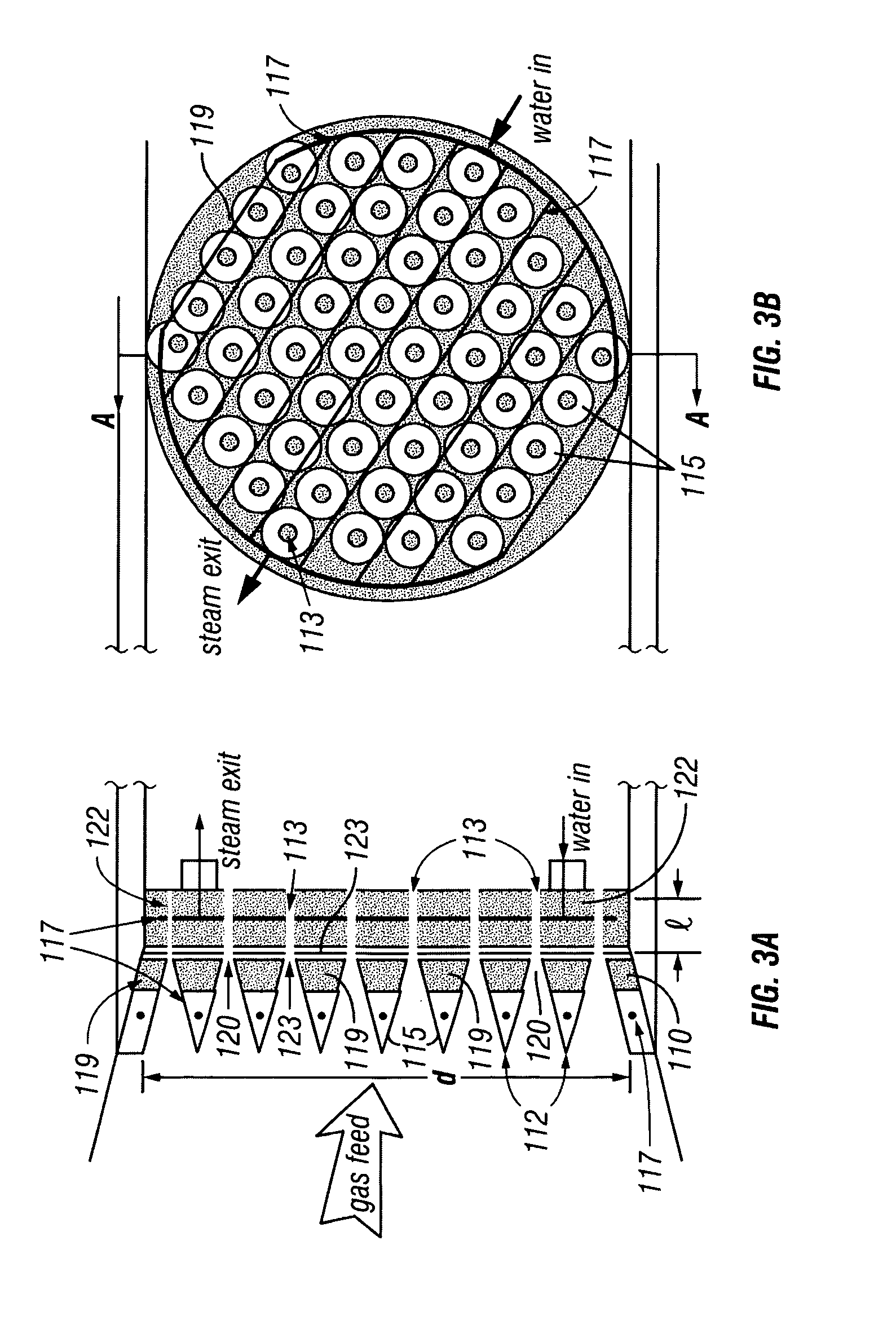
[0042]A third embodiment, a multi-hot wall funnel reactor, is depicted in FIGS. 3A and 3B. This embodiment includes a body 110 having a diameter d and an array of a plurality of comparatively small fore-funnels 112 to supply increased contact area for heating the gas. Each fore-funnel 112 corresponds and leads to an associated cooling channel 113 for cooling the gas of interest. The forward or “upstream” portion of each of the fore-funnels 112 is composed of highly reflecting metal portion 115, appearing as reflective annuli in FIG. 3B. The fore-funnels 112 are water-cooled in a mostly ordinary manner, by coolant flowing through water channels 117 also as shown in FIGS. 3A and 3B. The downstream, rearward or throat end portion 119 of each of the fore-funnels 112 is fashioned of high-temperature ceramic, such as ZrO2 or the like. The optical energy is intensified near the small-aperture throat 120 of each fore-funnel 112, and creates very hot walls in each fore-funnel for heating and...


PUM

PropertyMeasurementUnit
sizeaaaaaaaaaa
diameteraaaaaaaaaa
reflectivityaaaaaaaaaa

Abstract

Solar-powered reactor for processing of slightly absorbing and transparent gases. An obvious path to providing storable, renewable energy is through solar dissociation of gas molecules. These dissociation products are the precursors of modern liquid and gaseous fuels such as hydrogen and methanol / ethanol. An apparatus and method using a solar concentrator (such as a focusing trough or dish) directed at the receiving end of a reactor are disclosed. A range of designs of reactors for the dissociation of gases, both those that absorb slightly in the visible spectrum and those that are transparent in the visible and only absorb in the infrared, is described. For slightly-absorbing gases, a funnel-shaped reactor that preheats the gas and concentrates sunlight is the indicated embodiment. A system for dissociating CO2 using the invention is described. For transparent gases, a holraum embodiment is more appropriate for coupling solar energy into the gas. In both cases, heat from the hot stream of dissociated gas may also be used to produce electricity with a standard steam or Stirling cycle generator.

Description

CROSS-REFERENCE TO RELATED APPLICATIONS[0001]This application claims the benefit of the filing of U.S. Provisional Patent Application Ser. No. 60 / 360,589, entitled Solar Processing of Grey or Transparent Gases, filed on Mar. 1, 2002, and the specification thereof is incorporated herein by reference.BACKGROUND OF THE INVENTION[0002]1. Field of the Invention (Technical Field):[0003]The present invention relates to the use of solar energy for the processing of gases, particularly for the thermal dissociation of gases, and specifically for a method and apparatus for processing slightly-absorbing or transparent gases, including CO2, CH4, H2O and combinations thereof, and others.[0004]2. Background Art[0005]The industrialized world presently relies heavily on fossil fuels for its energy. The very large-scale combustion of these fuels causes a number of environmental concerns, including accumulation of carbon dioxide (CO2) in the Earth's atmosphere. Much of the demand is for convenient-to-...

Claims


Application Information

Patent Timeline
Patent Type & Authority Patents(United States)
IPC IPC(8): B60K16/00B01J19/08C10J3/20
CPCB01J19/127C01B3/04C01B3/042C10J3/00F24J2/07B01J2219/0869B01J2219/0871B01J2219/0875B01J2219/1203B01J2219/182B01J2219/1946C10J2300/1292Y02E10/41Y02E60/364F24S20/20Y02E10/40Y02E60/36Y02P20/133
Inventor JENSEN, REEDTRAYNOR, ANN J.
Owner SUNDROP FUELS
Learn More