Modular thread connection with high fatigue resistance

Active Publication Date: 2006-12-19
BAKER HUGHES INC
View PDF12 Cites 6 Cited by
  • Summary
  • Abstract
  • Description
  • Claims
  • Application Information

AI Technical Summary

Benefits of technology

[0005]The present invention provides a threaded connection having high resistance against cyclical bending fatigue. In a preferred embodiment, the threaded connection is used in a pin-box arrangement that joins two drill string components. Such components include, but are not limited to, steerable assemblies, drilling motors, bottomhole assemblies, measurement-while-drilling assemblies, formation evaluation tools, drill collars or drill pipe. In addition to complementary threads, the pin and box each include a radial shoulder and abutting surface, respectively. The threads of the pin and box conform to a pre-determined profile that is defined at least by taper, pitch, and root radius. A preferred thread profile includes a relatively long pitch, a relatively large root radius and a relatively shallow taper as compared to conventional thread profile standards (e.g., API standards). The thread configuration

Problems solved by technology

In certain instances, drilling activity may cause the string and BHA to bend.
It is, of course, also known that cyclical bending stresses imposed by even moderate loadings may lead to failure of the threaded connection (e.g., high cycle fatigue).
The harsh drilling conditions of the well bore environment or deviated well bores can cause such cyclical bending stresses in these threaded connections.
Unfortunately, conventional threaded connections, such as those specified by the American Petroleum Institute (API), do not always possess sufficient bending fatigue resistance to support advanced drill

Method used


Image

  • Modular thread connection with high fatigue resistance
  • Modular thread connection with high fatigue resistance
  • Modular thread connection with high fatigue resistance

Examples


Embodiment Construction

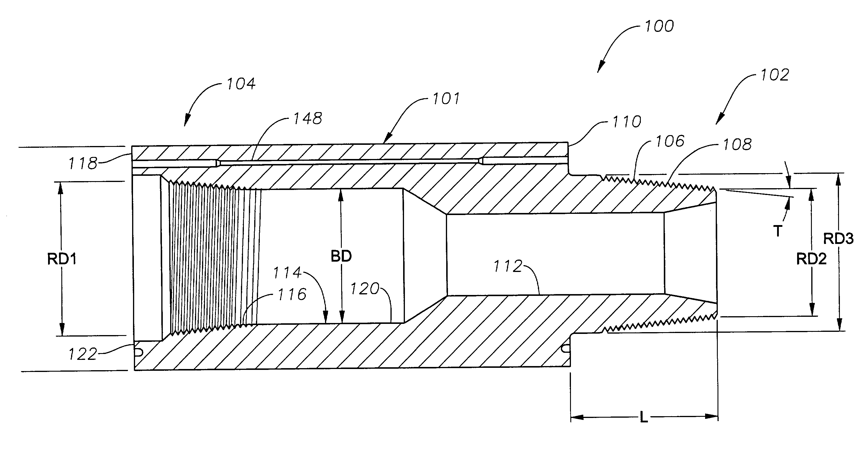
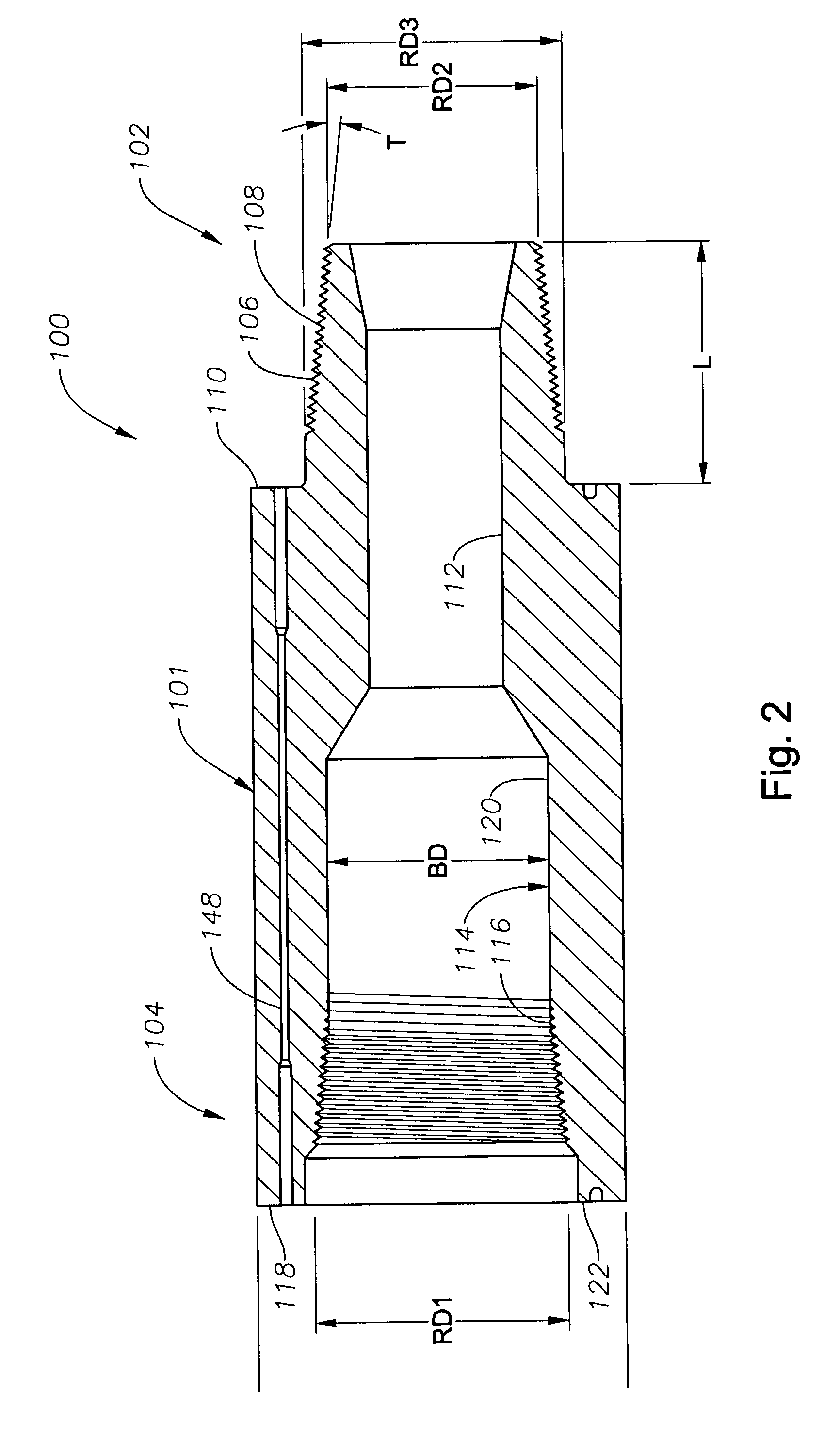
[0013]The present invention relates to an apparatus and methods for increasing the fatigue resistance of pin and box connections or couplings subjected to cyclic bending stresses, particularly in oilfield applications. The present invention is susceptible to embodiments of different forms. There are shown in the drawings, and herein will be described in detail, specific embodiments of the present invention with the understanding that the present disclosure is to be considered an exemplification of the principles of the invention, and is not intended to limit the invention to that illustrated and described herein.

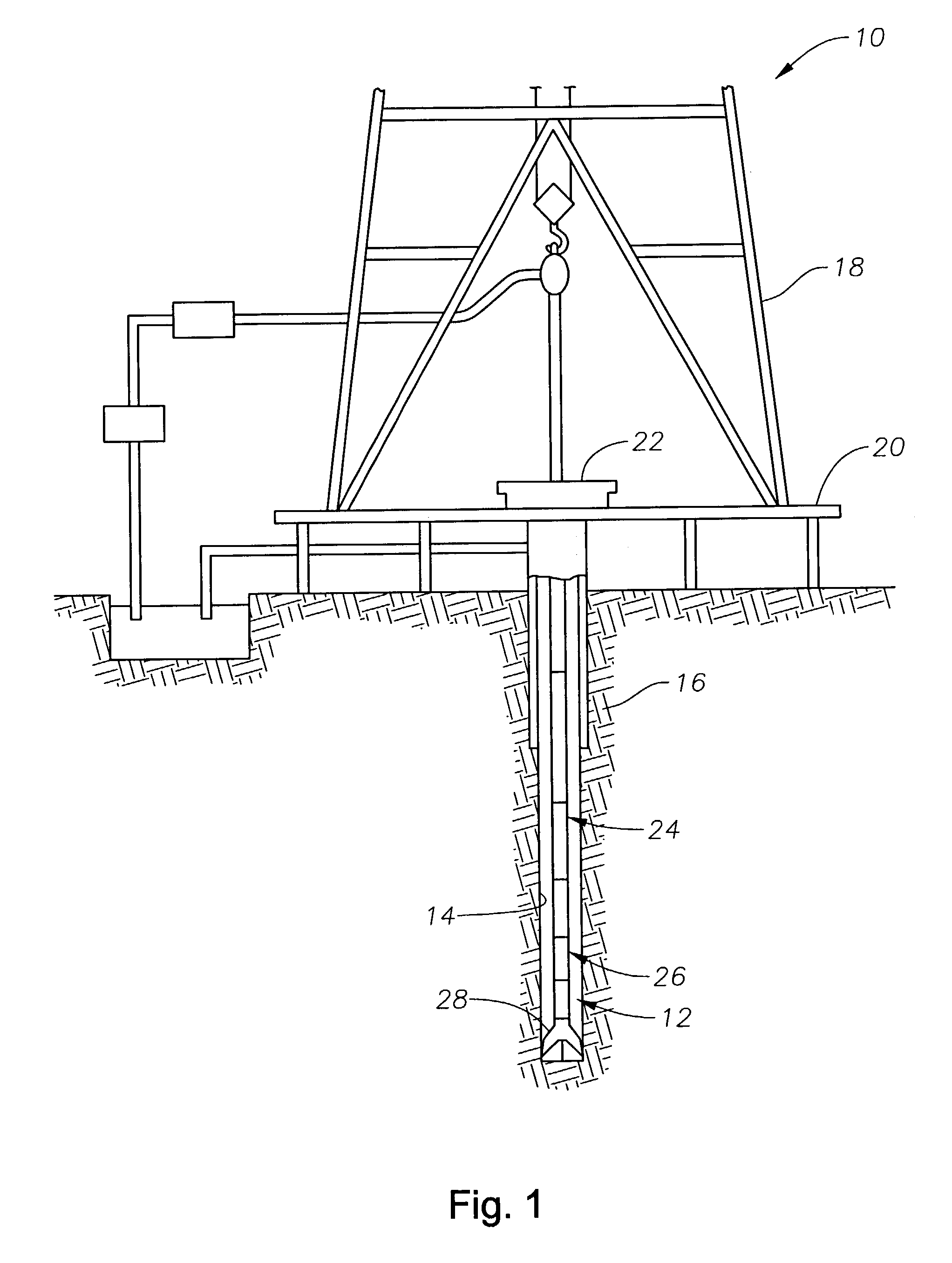
[0014]Referring initially to FIG. 1 there is shown a schematic diagram of a well construction system 10 having one or more well tools 12 shown conveyed in a borehole 14 formed in a formation 16. The system 10 includes a conventional derrick 18 erected on a floor 20 that supports a rotary table 22 that is rotated by a prime mover such as an electric motor (not shown) at a des...


PUM


Abstract

A connector for oilfield applications has high resistance against cyclical bending stress and fatigue failure. In a preferred embodiment, the threaded connector has a pin-box arrangement for joining two components. The pin and box have threads with a pre-determined profile different from that specified by conventional (e.g., API) specification and provide improved strength characteristics. Certain embodiments of the present invention include a pitch-to-root radius ratio that is less than that specified by the API, a thread height-to-root radius ratio that is less than that specified by the API, a flank angle that is less than that specified by the API, and a taper that is less than that specified by the API for said pre-determined outside diameter. Certain other embodiments have less than all of these ratios and dimensions. Optionally, the connector has (a) wiring for transmitting power and/or data through the connector; and (b) at least one seal disposed adjacent the wiring for protecting the wiring from contact with wellbore fluids.

Description

CROSS-REFERENCE TO RELATED APPLICATIONS[0001]This application takes priority from U.S. Provisional Patent Application Ser. No. 60 / 340,756, filed Dec. 7, 2001.BACKGROUND OF THE INVENTIONBackground of the Art[0002]Threaded connections are a prevalent method to join two or more members such as pipe sections. In certain applications, as during hydrocarbon exploration and recovery operations, a string of pipe sections joined by threaded connections may be rotated in a well bore. For example, a drill string may be rotated to urge a bottomhole assembly into a subterranean formation. The bottomhole assembly (BHA) also may include components that are mated or joined with threaded connections. In certain instances, drilling activity may cause the string and BHA to bend. As is known, the bending of threaded connection induces compression on one side of the threaded connection and a tension on the other side of the threaded connection. Because the threaded connection is rotating, the tension an...

Claims


Application Information

Patent Timeline
IPC IPC(8): F16L25/00E21B17/042
CPCE21B17/028E21B17/042
Inventor BENEDICT, DETLEVDUBER, HARALDFLORKE, HELMUT
Owner BAKER HUGHES INC
Why Eureka
Try Eureka