High-frequency power amplifier

a power amplifier and high-frequency technology, applied in high-frequency amplifiers, solid-state devices, gain control, etc., can solve the problems of reducing the sensitivity of the receiver of the mobile telephone, increasing the number of pa modules, and increasing the number of components of the pa module, so as to achieve the effect of low rx level

Active Publication Date: 2006-12-26
PANASONIC SEMICON SOLUTIONS CO LTD
View PDF20 Cites 75 Cited by
  • Summary
  • Abstract
  • Description
  • Claims
  • Application Information

AI Technical Summary

Benefits of technology

[0026]Therefore, an object of the present invention is to provide a compact and low-cost high-frequency power amplifier including GaAs HBTs but having a low Rx level.

Problems solved by technology

However, the PA module including the GaAs FETs requires a power supply for applying negative bias voltage to a gate electrode, resulting in an increase in number of components of the PA module, and making it difficult to reduce the size, weight, and cost of the mobile telephones.
If noise in a reception band (Rx noise) outputted from the PA module is greater than a predetermined value, the receiver sensitivity of the mobile telephone is reduced, adversely affecting the reception efficiency.
However, in recent years, the GaAs FETs used in the PA modules have been replaced by the GaAs HBTs, attracting attention on adverse effects of the RX noise on the receiver sensitivity of mobile telephones.
As a result, it was found that in the conventional PA module using the GaAs HBTs, the Rx noise is at such a level as to adversely affect the receiver sensitivity of the mobile telephones.
As compared to before, the duplexers are becoming unsatisfactory in terms of attenuation levels in the reception band.
In particular for the PA module using the GaAs HBTs, which generally has a higher Rx level than the PA module using the GaAs FETs, the above problem related to the Rx noise requires urgent resolution.

Method used


Image

  • High-frequency power amplifier
  • High-frequency power amplifier
  • High-frequency power amplifier

Examples


first embodiment

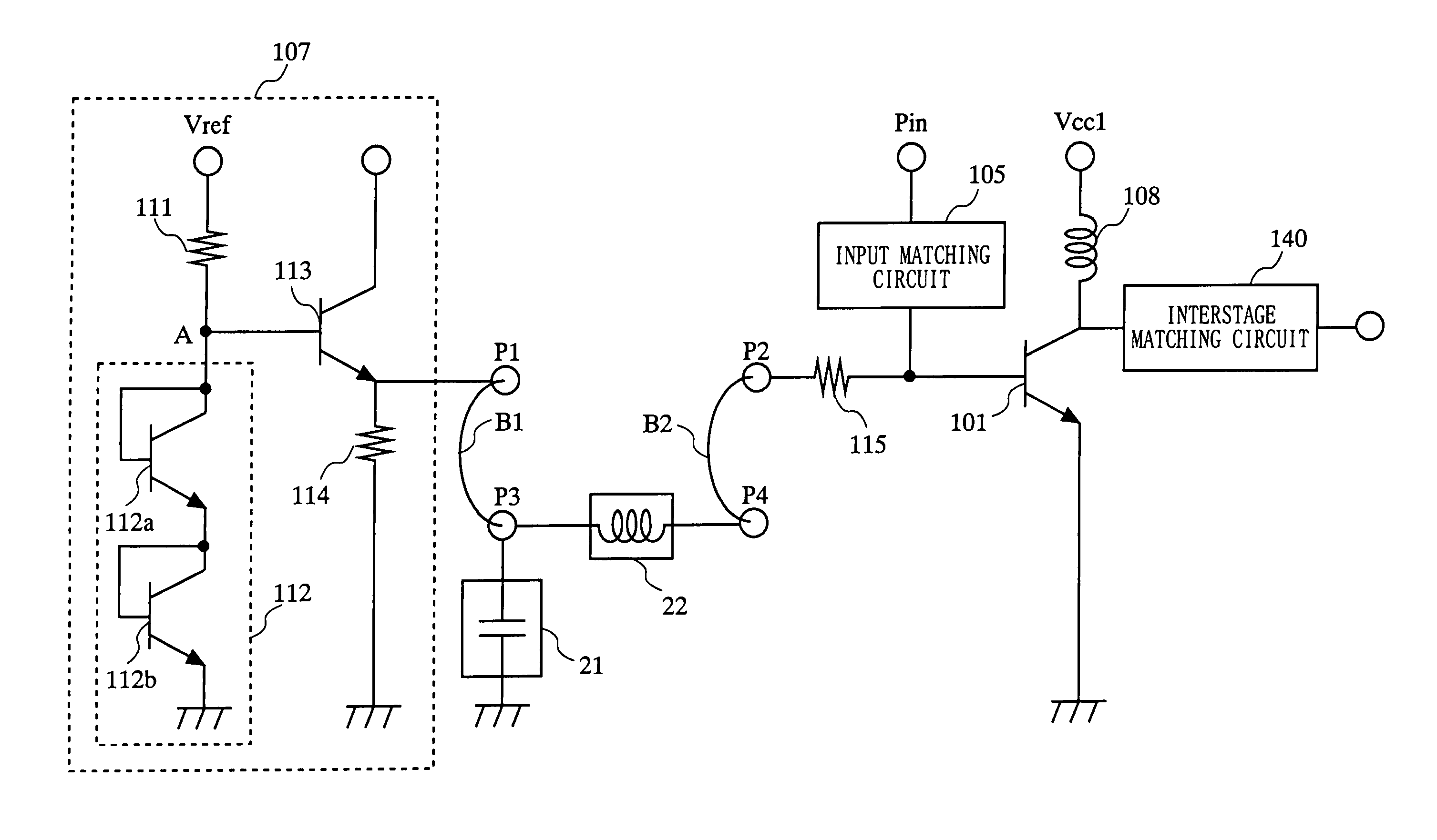
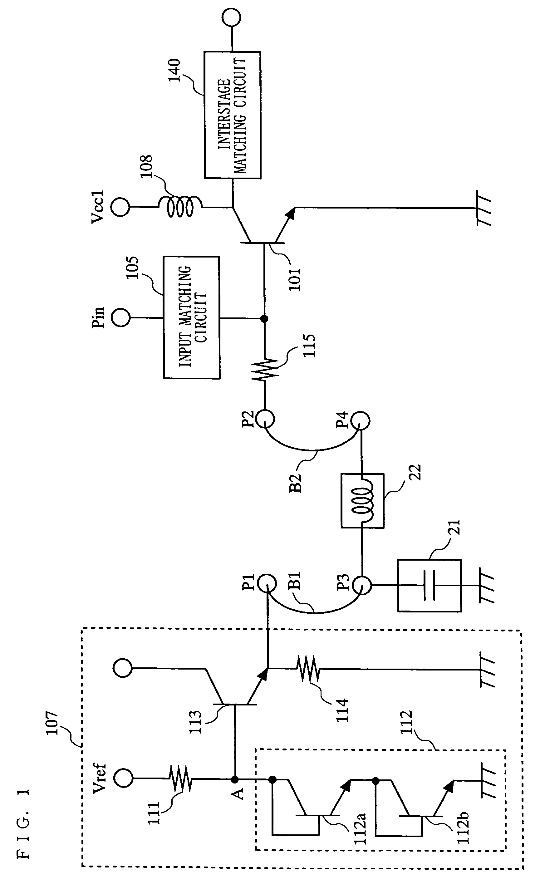
[0058]FIG. 1 is a circuit diagram of a high-frequency power amplifier according to the present invention. The high-frequency power amplifier according to the present embodiment includes a high-frequency signal amplification HBT 101, an input terminal Pin, earth terminals, a collector power supply terminal Vcc1, a choke coil 108, an upstream stage bias circuit 107, an input matching circuit 105, an interstage matching circuit 140, a chip capacitor 21, a chip inductor 22, bonding wires B1 and B2, pads P1 through P4, and a resistor 115. The chip capacitor 21 and the chip inductor 22 included in the high-frequency power amplifier shown in FIG. 1 reduce Rx noise that is generated within the high-frequency power amplifier.

[0059]As shown in FIG. 1, the upstream stage bias circuit 107 includes a reference voltage terminal Vref, resistors 111 and 114, earth terminals, a temperature compensation circuit 112, and a direct current supply HBT 113. The resistor 111 and the temperature compensatio...

fourth embodiment

[0092]As described in relation to the present invention, the spiral inductor 32 and a resistor are used to accurately provide necessary resistance between the direct current supply HBT 113 and the high-frequency signal amplification HBT 101. However, depending on the type of the resistor, noise might by generated by the resistor, so that the noise increases the Rx noise level.

[0093]In order to solve such a problem, the high-frequency power amplifier according to the present embodiment includes the resistor 119 between the emitter electrode of the direct current supply HBT 113 and the pad P1, such that the chip capacitor 21 causes noise generated at the resistor 119 to flow to the ground. This reduces the noise generated at the resistor 119, thereby reducing the Rx noise level.

[0094]An experiment was carried out with a PA module with a downstream stage amplification section connected to the high-frequency power amplifier according to the present embodiment. Also, for comparison purpo...


PUM


Abstract

The present invention provides a compact and low-cost high-frequency power amplifier including GaAs heterojunction bipolar transistors (HBTs) but having a low level of noise in the transmission band. In the high-frequency power amplifier of the present invention, a chip capacitor 21 is connected at one end to an upstream stage bias circuit 107 via a bonding wire B1, and grounded at the other end. Also, a chip inductor 22 is connected to a base electrode of a high-frequency signal amplification HBT 101 via a bonding wire B2. In the high-frequency power amplifier of the present invention, the chip capacitor 21 causes noise generated within the upstream stage bias circuit 107 to flow to the ground, thereby reducing noise in the reception band. Also, the chip inductor 22 reduces a power loss of a high-frequency signal which is caused because the high-frequency signal flows to the ground.

Description

BACKGROUND OF THE INVENTION[0001]1. Field of the Invention[0002]The present invention relates to a high-frequency power amplifier, and more particularly to a high-frequency power amplifier for use in mobile communication equipment including mobile telephones.[0003]2. Description of the Background Art[0004]In recent years, mobile telephones have become indispensable to our lives not only as calling tools but also as communication tools for exchanging E-mails, content, etc. Currently, the most prevalent mobile telephone communication systems used in the world are the second generation communication systems. In Japan, the personal digital cellular (PDC) system is widely used; in North America, the code division multiple access (CDMA) system is widely used; in Europe, the global system for mobile (GSM) system is widely used.[0005]It is expected that in the near future, the market for mobile telephones will experience a transition to the third communication systems, such as the wideband ...

Claims


Application Information

Patent Timeline
Patent Type & Authority Patents(United States)
IPC IPC(8): H03G3/10H03F3/24H03F1/02H03F1/30H03F3/19H03F3/20
CPCH03F1/302H01L2223/665H01L2224/48227H01L2224/48091H01L2924/00014H03F1/30H03F3/20
Inventor MAEDA, MASAHIRO
Owner PANASONIC SEMICON SOLUTIONS CO LTD
Why Eureka
Try Eureka