CNT film and field-emission cold cathode comprising the same

a cold cathode and cnt film technology, applied in the manufacture of discharge tube main electrodes, electrode systems, electric discharge tubes/lamps, etc., can solve the problems of affecting the upright state of the discharge tube, impairing the excellent characteristics of the electric field concentration, and it is extremely difficult to implement uniform emission characteristics at low voltage. , to achieve the effect of excellent emission characteristics

Inactive Publication Date: 2007-01-09
NEC CORP
View PDF12 Cites 24 Cited by
  • Summary
  • Abstract
  • Description
  • Claims
  • Application Information

AI Technical Summary

Benefits of technology

[0075]Since the field emission cold cathode formed as described above is applied to the flat image display device according to the eleventh aspect, the present invention can provide excellent emission characteristics.

Problems solved by technology

To fabricate a flat image display device such as FEDs using the aforementioned triode structure, an insulating film is formed on a CNT film and an opening is then formed in the insulating film using an etching solution or an etching gas or the like, wherein those CNTs that stand upright near the surface of the CNT film may disappear due to the influence of the etching solution or the etching gas, thereby impairing excellent characteristics of electric field concentration.
With this method, for example, most CNTs 112a on the CNT film surface lie down toward the substrate surface due to the viscosity and the surface tension of the binder solution or are buried in the binder, thereby impairing their upright states and making it extremely difficult to implement uniform emission characteristics at low voltages.
When the surface of the CNT film 112 is coated with this insulating material, the surface barrier of electrons is substantially increased upon emission of the electrons, thereby significantly reducing the emission efficiency.

Method used


Image

  • CNT film and field-emission cold cathode comprising the same
  • CNT film and field-emission cold cathode comprising the same
  • CNT film and field-emission cold cathode comprising the same

Examples


first embodiment

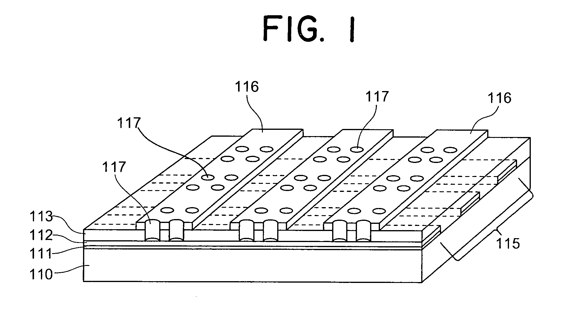
[0109]FIG. 1 is a perspective view illustrating a flat image display device such as a FED with an emitter to which applied is a CNT film fabricated by a fabrication method according to the present invention.

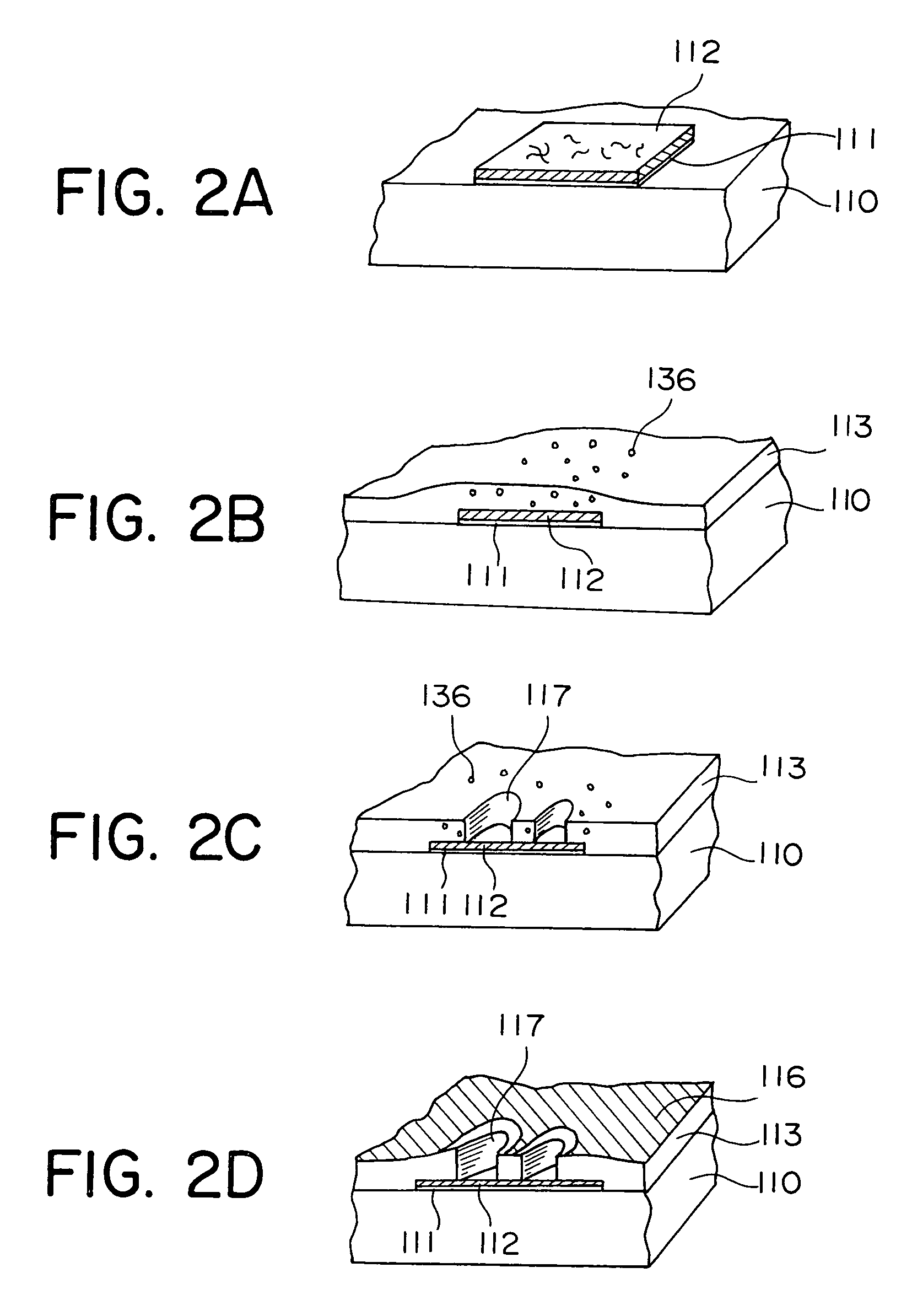
[0110]The flat image display device has on a glass substrate 110 a plurality of stripe-shaped conductive layers 111 which extend in the right to left direction of FIG. 1 in parallel to each other. Each of the conductive layers 111 has a CNT film 112 of the same width deposited thereon, respectively, to form cathode (emitter) lines 115. Additionally, SOG (Spin On Glass), polyimide, acrylic resin or the like is dispensed and coated (spin coated) so as to cover the entire surface of the glass substrate 110 containing the CNT film 112, thereby forming a gate insulating film 113.

[0111]On the gate insulating film 113, stripe-shaped gate electrodes 116 extend in parallel to each other and perpendicular to the cathode lines 115 to form gate lines. At the intersections of the cathode line...

second embodiment

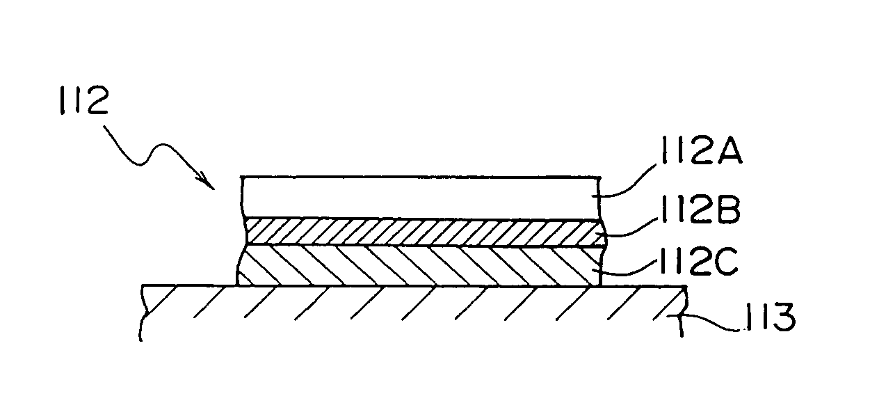
[0174]Now, a fabrication method according to the present invention is explained. Referring to FIG. 14, the CNT film 112 is divided into three stages in the direction of thickness: a first layer 112A, a second layer 112B, and a third layer 112C.

[0175]The CNT film 112 contains the CNTs 112a and particulate impurities, and can be impregnated with an organic binder material such as acrylic, nitrocellulose, and polyimide resin in order to increase its mechanical strength and improve the characteristics of adhesion to the glass substrate 110. The reason why the organic binder was employed here is because it can be baked through a low-temperature process (at 300 degrees or less) and the CNT film can be easily patterned as described later. In view of these points, in this embodiment, the composition ratio is adjusted for each of the three portions of the CNT film 112.

[0176]The first layer 112A constituting an electron emitting surface employed a ratio at which the upright aligned CNTs 112a ...

third embodiment

[0181]Now, a fabrication method according to the present invention is explained. Referring to FIG. 15, in the process for patterning the CNT film, the surface of a portion having to remain in the CNT film 112 is covered with a mask material 139 while a portion 138 having to be removed is dissolved in acetone or the like to thereby be removed. In this case, CNTs and particulate impurities are not dissolved in acetone, but the acrylic is dissolved.

[0182]Using the aforementioned method, the length of the contained CNTs is made shorter than the distance between gaps to be removed by patterning, thereby making it possible to perform patterning without raising a problem of causing the remaining CNTs to be bridged thereby disabling separation.

[0183]For the CNTs longer than the gap distance, the gap portion is mechanically rubbed so as to prevent bridging of the CNTs, thereby making it possible to remove the CNTs bridged temporarily. In this case, since the binder supporting the CNTs is dis...


PUM

PropertyMeasurementUnit
particle diameteraaaaaaaaaa
diameteraaaaaaaaaa
diameteraaaaaaaaaa

Abstract

A fabrication method for an emitter includes the steps of forming on a glass substrate a CNT film which contains a plurality of carbon nanotubes (CNTs) and constitutes an emitter electrode, forming a gate electrode via an insulating film on the CNT film, forming a plurality of gate openings in the gate electrode and the insulating film, and aligning upright the CNTs in the gate opening. The upright alignment generates a stable uniform emission current and provides excellent emission characteristics.

Description

TECHNICAL FIELD[0001]The present invention relates to a method for fabricating an field emission cold cathode used in a flat display device (flat image display device) such as a field emission display (hereinafter also referred to as a “FED”), and more particularly to a fabrication method for easily fabricating an emitter, that can make use of excellent emission characteristics, upon using carbon nanotubes (hereinafter also referred to as “CNTs”) as film-shaped emitters. The present invention also relates to a CNT film for use with such a field emission cold cathode and a method for fabricating the same.BACKGROUND ART[0002]In recent years, a carbon nanotube or a new carbon material is prospective particularly in the application as an emitter material such as for a field emission cold cathode. A CNT has the shape of a hollow cylinder of a graphene sheet which has regularly arranged carbon atoms and which is formed in a tubular shape, and is a very high aspect ratio microscopic materi...

Claims


Application Information

Patent Timeline
Patent Type & Authority Patents(United States)
IPC IPC(8): H01J1/14D01F9/12H01J1/146H01J9/04H01J9/02
CPCB82Y10/00H01J9/025H01J2201/30469Y10S977/753Y10S977/842Y10S977/844Y10S977/939Y10S977/742
Inventor OKAMOTO, AKIHIKOKONUMA, KAZUOTOMIHARI, YOSHINORIITO, FUMINORIOKADA, YUKO
Owner NEC CORP
Why Eureka
Try Eureka