Vascular treatment device and method

a treatment device and vascular technology, applied in the field of vascular treatment devices and methods, can solve the problems of affecting the patient's recovery, and unable to prevent the backflow of blood into the superficial veins, so as to reduce the trauma, pain and post-operative bruising of the patient, and achieve substantial time and cost savings

Inactive Publication Date: 2007-01-16
ANGIODYNAMICS INC
View PDF12 Cites 48 Cited by
  • Summary
  • Abstract
  • Description
  • Claims
  • Application Information

AI Technical Summary

Benefits of technology

[0018]By administering the fluids from within the catheter lumen, the present invention eliminates the need to make numerous external punctures to deliver tumescent injections. As a result, the invention provides substantial time and cost savings to a treating physician while reducing the trauma, pain and post-operative bruising of the patient.

Problems solved by technology

When the valves are malfunctioning or only partially functioning, however, they no longer prevent the back-flow of blood into the superficial veins.
As a result, venous pressure builds at the site of the faulty valves.
Symptoms include discomfort, aching of the legs, itching, cosmetic deformities, and swelling.
If left untreated, varicose veins may cause medical complications such as bleeding, phlebitis, ulcerations, thrombi and lipodermatosclerosis.
While providing temporary relief of symptoms, these techniques do not correct the underlying cause, that is the faulty valves.
Even with its high clinical success rate, surgical excision is rapidly becoming an outmoded technique due to the high costs of treatment and complication risks from surgery.
The procedure is done on an outpatient basis, but is still relatively expensive due to the length of time required to perform the procedure.
Although a popular treatment option, complications can be severe including skin ulceration, anaphylactic reactions and permanent skin staining.
Another disadvantage is that treatment is limited to veins of a particular size range.
In addition, there is a relatively high recurrence rate due to vessel recanalization.
Second, the injection causes the vein to spasm which reduces the diameter of the vein and brings the vessel wall in close proximity to the catheter and the optical fiber.
The gas bubbles transfer thermal energy to the vein wall, causing cell necrosis and eventual vein collapse.
The damaged vessel becomes occluded, collapses and can no longer support blood flow.
However, there are several disadvantages associated with such a conventional method of administering local anesthesia injections.
The anesthetic injection process is cumbersome and is the most time-consuming step in the treatment procedure because of the number of punctures that has to be made.
In addition to the time required to administer multiple injections, peri-venous injections are disadvantageous because they are painful to the patient, leave puncture wounds, and may increase bruising and post-procedure complications because of the way the injection is administered.
In some cases, a physician may inadvertently puncture the vein and even the catheter wall when positioning the needle.
When this occurs, the vein wall may be lacerated resulting in excessive bruising and patient discomfort.
Lacerations of the vein wall may also result in non-targeted thermal damage outside of the vessel as the gas bubble created by the laser may escape through the laceration into the adjoining tissue and nerve structures.
Another disadvantage is that needle punctures that penetrate the catheter wall may damage the integrity of the catheter and / or the optical fiber.
The medical staff performing the procedure is thus at an increased risk of accidental needle sticks and the potential health hazards associated with unintentional exposure to contaminated blood and other body fluids.

Method used


Image

  • Vascular treatment device and method
  • Vascular treatment device and method
  • Vascular treatment device and method

Examples


Embodiment Construction

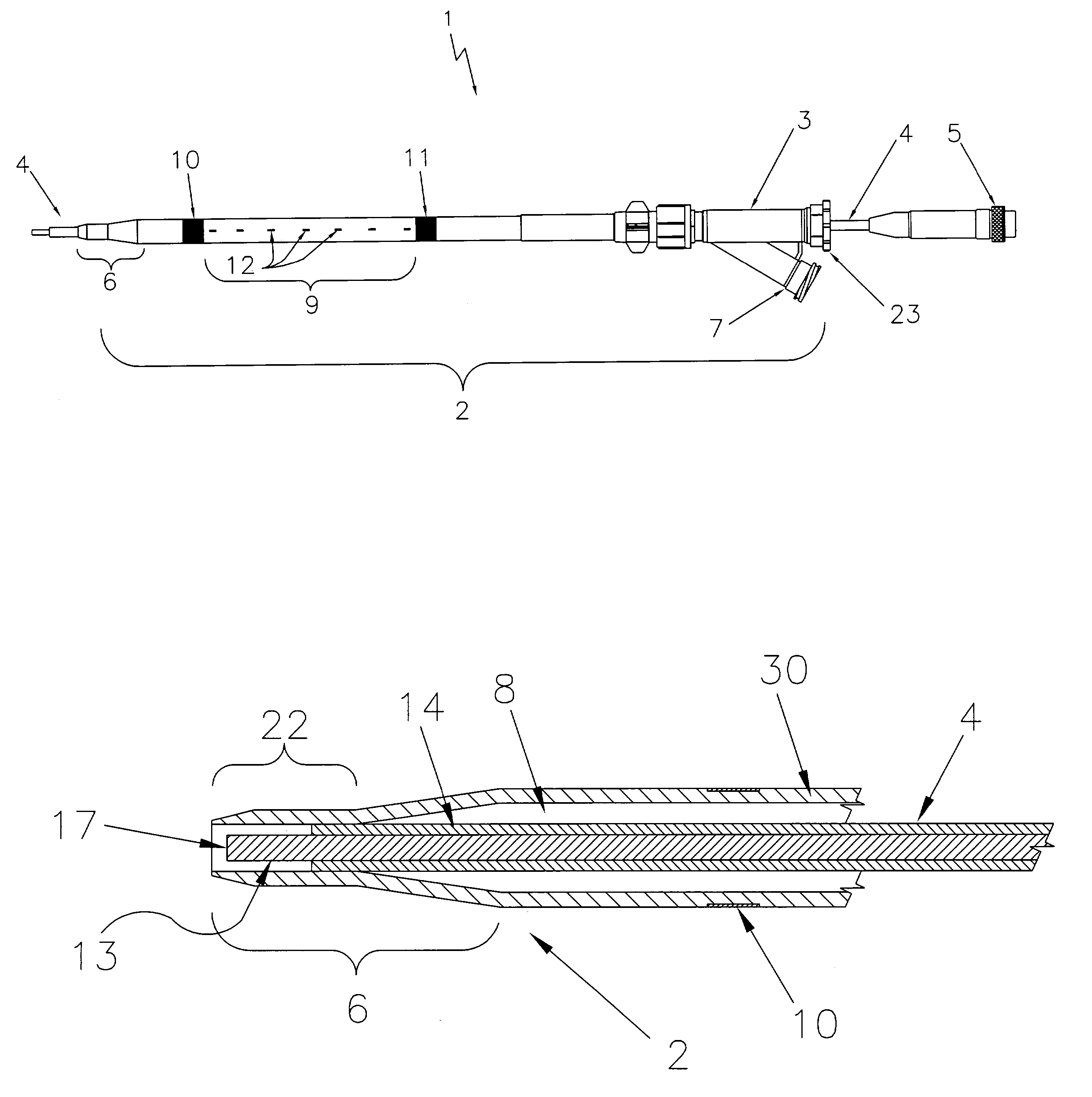
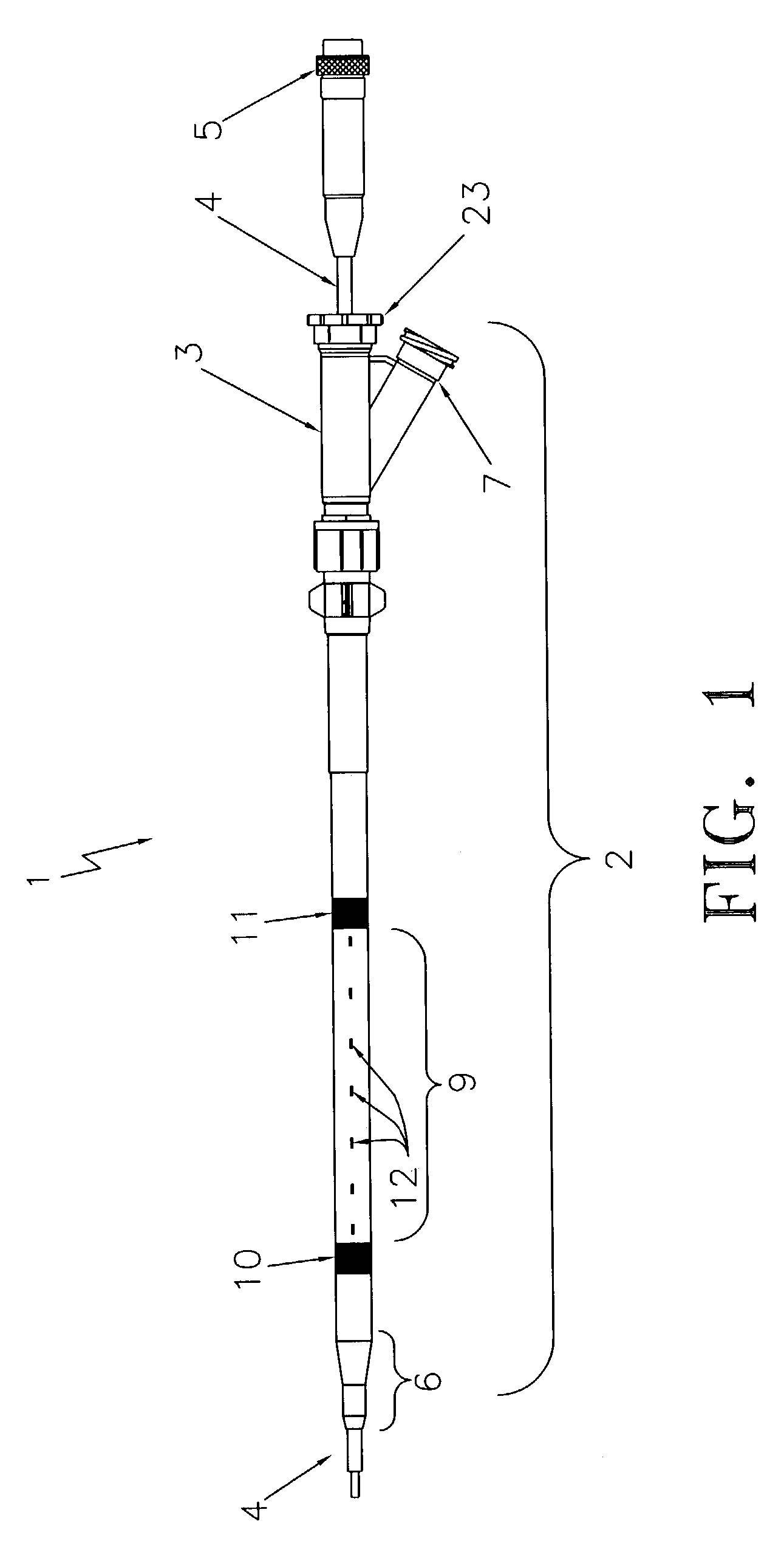
[0031]An endovascular laser treatment device 1 according to the present invention is illustrated in FIG. 1. It is to be noted that the device 1 is illustrated with only a laser optical fiber for purposes of clarity only. Other types of energy delivery source such as RF electrodes can also be used with the present invention.

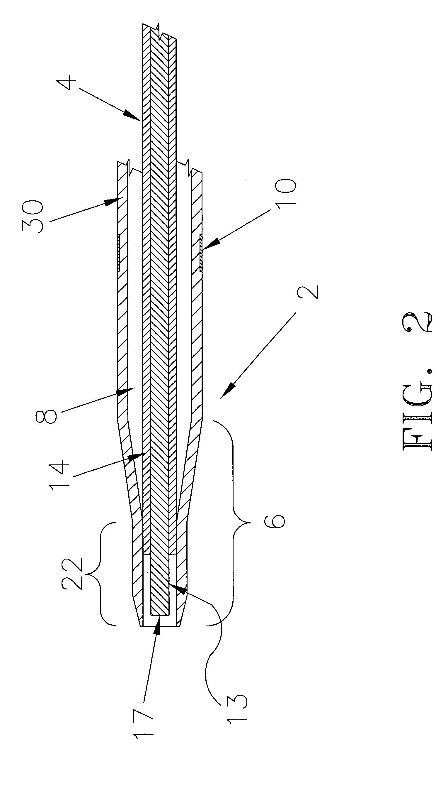
[0032]The laser treatment device 1 includes an infusion catheter assembly 2 having a Y-connector 3, and an optical fiber 4 having a SMA connector 5. The catheter 2 is a tubular structure used to facilitate the passage of the optical fiber 4 within the cardiovascular system of a patient. Referring to FIGS. 1–3, the catheter 2 has a catheter tip section 6 with a through-lumen 8 for insertion and passage of the optical fiber 4. The catheter tip section 6 is defined by an occluding zone 22 shown in FIGS. 2–3. When the optical fiber 4 is inserted and advanced through the catheter lumen 8 into the occluding zone 22, the optical fiber 4 in contact with an inner wall of t...


PUM


Abstract

A catheter device for treating a vascular disease is provided. The catheter device includes an energy delivery device such as an optical fiber for delivering laser energy and a catheter. The catheter lumen receives the optical fiber and a fluid such as an anesthetic agent or vasoconstricting agent. According to the invention, a plurality of exits are formed in the sidewall of the catheter. The exits are in communication with the catheter lumen and administer the fluid into the blood vessel. By administering the fluid from within the catheter lumen, the present catheter device eliminates the need to make numerous external punctures to deliver fluid injections.

Description

CROSS-REFERENCE TO RELATED APPLICATIONS[0001]This application claims priority to U.S. Provisional Application No. 60 / 370,050, filed Apr. 4, 2002, which is incorporated herein by reference.FIELD OF THE INVENTION[0002]The present invention relates to a medical device for treatment of vascular diseases, and more particularly, to a device for treating varicose veins using an endovascular laser optical fiber and catheter.BACKGROUND OF THE INVENTION[0003]Veins are thin-walled and contain one-way valves that control blood flow. Normally, the valves open to allow blood to flow into the deeper veins and close to prevent back-flow into the superficial veins. When the valves are malfunctioning or only partially functioning, however, they no longer prevent the back-flow of blood into the superficial veins. As a result, venous pressure builds at the site of the faulty valves. Because the veins are thin walled and not able to withstand the increased pressure, they become what are known as varicos...

Claims


Application Information

Patent Timeline
Patent Type & Authority Patents(United States)
IPC IPC(8): A61B18/18A61B18/20A61B17/22A61B18/24A61M25/00
CPCA61B18/245A61M25/0075A61B17/00008A61B2017/00778A61M2025/0076A61M25/007A61B2017/22082
Inventor HOBBS, EAMONNAPPLING, WILLIAM M.
Owner ANGIODYNAMICS INC
Why Eureka
Try Eureka