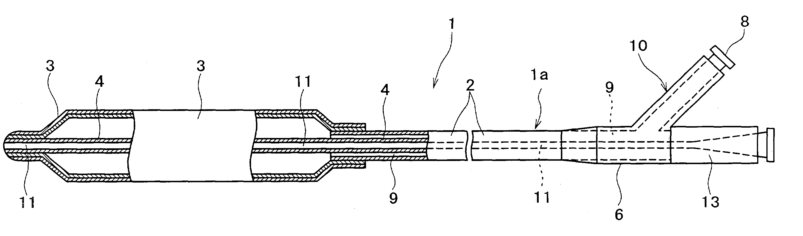
Balloon catheter

a balloon catheter and balloon technology, applied in the direction of catheters, pedestrian/occupant safety arrangements, vehicular safety arrangements, etc., can solve the problems of insufficient impregnation, defects not impregnated with resin, prone to occur, etc., to reduce the occurrence of pin holes and cracks, improve the strength of the balloon, and enhance the withstand pressure

Active Publication Date: 2007-02-06
TERUMO KK
View PDF8 Cites 27 Cited by
  • Summary
  • Abstract
  • Description
  • Claims
  • Application Information

AI Technical Summary

Benefits of technology

[0027]Accordingly, since the entire balloon is reinforced with the short-fibers, the strength of the entire balloon is improved. As a result, it is possible to provide a balloon capable of reducing occurrence of pin-holes and cracks and enhancing the withstand pressure, and to provide a balloon catheter including such a balloon. Also, since the flexibility of the balloon can be sufficiently kept, it is possible to provide a balloon excellent in trackability in a blood vessel, and to provide a balloon catheter including such a balloon.
[0028]In the case of subjecting the short-fibers to a surface modifying tre

Problems solved by technology

The composite material obtained by forming a resin integrally with such long-fibers or a fiber-structure of the long-fibers, however, has a disadvantage that it is generally difficult to sufficiently impregnate a gap between the adjacent single fibers in the yarn with the resin, to cause defects not impregnated with the resin.
In particular, in the case of using multi-filaments, such detects not impregnated with a resin are liable to occur.
Another disadvantage is that since the method disclosed in the above document requires the step of forming the fiber-structure into the shape of a balloon, if it is intended to produce a balloon having a fine diameter, the uniformity of production and the production yield may be degraded.
The extrusion method disclosed in the above-described document, however, has a disadvantage that since the reinforcing resin is disposed in the form of whiskers (pulp) in the matrix resin by discharging the reinforcing resin from a specific number of the discharge nozzles of the die while applying a rotational force and a shearing fo

Method used


Image

  • Balloon catheter
  • Balloon catheter
  • Balloon catheter

Examples


example 1

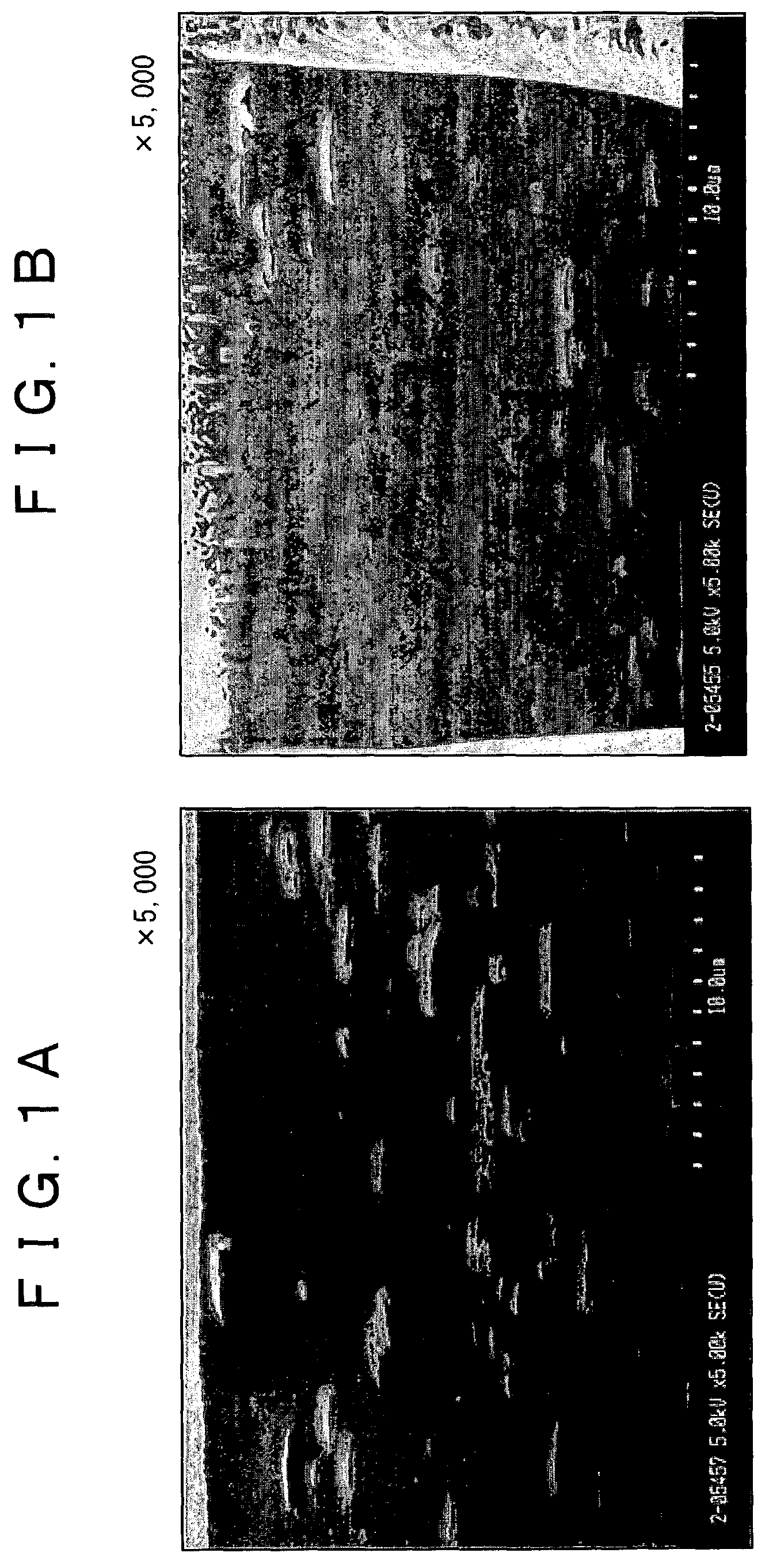
[0122]Using a biaxial kneader, carbon short-fibers (diameter: 7 μm, average length: 6 mm, aspect ratio: about 850) previously surface-treated by a titanium coupling agent and a polyamide elastomer resin (commercially available from EMS Japan Co., Ltd. in the trade name of Grilamid) are extruded and hot-cut at 220° C., to prepare kneaded pellets. The content of the carbon short-fibers is set to 18 wt % on the basis of the total amount of the polyamide elastomer. The lengths of the short-fibers become short by kneading (compounding), with a result that the average length of the carbon short-fibers in the matrix resin is in a range of 400 to 500 μm and the aspect ratio of each of the carbon short-fibers is in a range of 60 or more.

[0123]Outer and inner layers each of which is made from a polyamide elastomer resin and an intermediate layer made from the above-described fiber-blended polyamide elastomer resin are extruded into a tubular parison by the rotary extrusion molding machine (ha...

example 2

[0128]Nanocarbon tubes of a multi-layer type (outer diameter: 7 nm, length: about 80 nm) are blended in an amount of 15 wt % to a thermoplastic polyimide (commercially available from Mitsui Toatsu Chemicals, Inc. in the trade name of AURUM). To be more specific, the nanocarbon tubes are added in polyamic acid as a precursor of the polyimide in a solution polymerization step of the a precursor, and after formation of polyimide rings, a resin containing the nanocarbon tubes blended in the polymerization step is taken out.

[0129]The nanocarbon tube blended thermoplastic polyimide resin is molded into a tubular parison (wall thickness: 0.025 mm) by a known extrusion molding method. In addition, the drawdown ratio in cross-section between the die and tip upon extrusion molding is set to 8:1.

[0130]The parison is molded into a balloon (outer diameter: 3.0 mm) by a known biaxial orientation blow molding process using a balloon molding die, and the balloon is assembled into a PTCA balloon cat...

example 3

[0133]A polyurethane resin (commercially available from Dainippon Ink and Chemicals, incorporated in the trade name of “Pandex”) is dissolved in tetrahydrofuran at a concentration of 20%, and carbon short-fibers (diameter: 7 μm, average length: 6 mm, aspect ratio: about 850) are added in the polyurethane solution. The resultant polyurethane solution containing the carbon short-fibers is slowly stirred at 30° C. and is simultaneously irradiated with ultrasonic waves at a frequency of 38 KHz and a power of 600 W for 60 min by an ultrasonic transducer (commercially available from Ultrasonic Engineering Co., Ltd. in the trade name of “Model CM-121”).

[0134]A metal wire having an outer diameter of 1 mm covered with polytetrafluoroethylene (PTFE) is dipped in the short-fiber blended polyurethane solution having been subjected to the ultrasonic vibration treatment, and is then slowly pulled up and dried for 2 hr at 60° C. Such a step is repeated by several times, and finally the metal wire ...


PUM

PropertyMeasurementUnit
Fractionaaaaaaaaaa
Fractionaaaaaaaaaa
Luminous fluxaaaaaaaaaa

Abstract

A balloon catheter includes a long-sized body extending between a proximal end and a distal end, the body internally having at least one lumen, and a balloon made from a composite material composed of short-fibers for reienforcement and a matrix resin, the balloon being disposed on the distal side of the long-sized body. The short-fibers are oriented in the balloon in such a manner that in a longitudinal cross-section of the balloon, 25% or more of the short-fibers are oriented in the major-axis direction of the balloon, 25% or more of the short-fibers are oriented in the direction oblique to the major-axis direction, and the remaining short-fibers are oriented in the direction nearly perpendicular to the major-axis direction; and in a diametrical cross-section of the balloon, 8% or more of the short-fibers are oriented in the circumferential direction of the balloon, 25% or more of the short-fibers are oriented in the direction perpendicular to the circumferential direction, that is, in the major-axis direction, and the remaining short-fibers are oriented in the direction oblique to the circumferential direction. The balloon catheter exhibits a high strength to withstand pressure and a good trackability.

Description

BACKGROUND OF THE INVENTION[0001]The present invention relates to a balloon catheter for medical application, and particularly to a dilation balloon catheter to be inserted in a body cavity such as a blood vessel, which catheter has a dilation balloon to be very easily insertable in a narrow, eccentric or meandering stenosis portion, or a branch portion in the body cavity in order to dilate the stenosis portion.[0002]A dilation balloon catheter generally includes inner and outer tubes to be inserted in a body cavity and a cylindrical balloon connected to the inner and outer tubes.[0003]Such a cylindrical balloon has been required to satisfy inconsistent needs for a sufficient strength to withstand a pressure for dilation of the balloon and a good trackability in a blood vessel. Specifically, the dilation balloon has been required to have a characteristic easily insertable even in a very narrow, eccentric, or meandering stenosis portion without damaging the stenosis portion while kee...

Claims


Application Information

Patent Timeline
IPC IPC(8): B29D22/00B32B1/08B29D23/00A61L29/00A61L29/12A61M25/00
CPCA61L29/126Y10T428/1362Y10T428/1352Y10T428/1369Y10T428/1334
Inventor KINOSHITA, YASUSHIMURAYAMA, HIRAKU
Owner TERUMO KK
Why Eureka
Try Eureka