Method and apparatus for neutralization of ion beam using AC ion source

a technology of ac ion source and neutralization method, which is applied in the direction of mechanical apparatus, ion beam tubes, machines/engines, etc., can solve the problems of electrical breakdown, poor conductivity of inclusions or thin films, and introduction of defects at the substrate surfa

Inactive Publication Date: 2007-07-10
GENERAL PLASMA
View PDF3 Cites 28 Cited by
  • Summary
  • Abstract
  • Description
  • Claims
  • Application Information

AI Technical Summary

Problems solved by technology

This need is especially apparent for insulating substrates, but even conductive substrates as well as other surfaces of the apparatus frequently have poorly conducting inclusions or thin films on them.
If those films or inclusions are not discharged, the accumulated charge may lead to an electrical breakdown and an onset of an arc that may introduce defects at the substrate surface.
These closed drift ion sources are quickly finding new applications due to their rugged design and low maintenance.
A significant problem with the use of hot filament thermionic electron emitters is that the operational lifetime of the emitters can be very limited, often less than 100 hours.
An additional problem with an electron emitter neutralizer is that it can introduce additional complexity to the system, and perhaps, a need to align the position of the neutralizer so that it has good coupling with the plasma but does not stand in the way of the ion beam.
Yet another additional problem with an electron emitter neutralizer can be a non-uniformity that it may introduce onto the process, especially with wide aperture beams.
This type of electron emitter is typical of the complexity that some designs add to the process.
This method did not seem to be applicable to closed drift ion sources because a closed drift source cannot sustain its discharge with reversed bias voltage.
However, almost always all magnetic field lines originating at the anode terminate at the cathode, so reverse bias could force electrons to the positive side of the source before they can make any ionization.
Moreover, a shortened duty cycle appeared to cause reduction of the ion source throughput and this alone could make this method commercially unattractive.

Method used


Image

  • Method and apparatus for neutralization of ion beam using AC ion source
  • Method and apparatus for neutralization of ion beam using AC ion source
  • Method and apparatus for neutralization of ion beam using AC ion source

Examples


Embodiment Construction

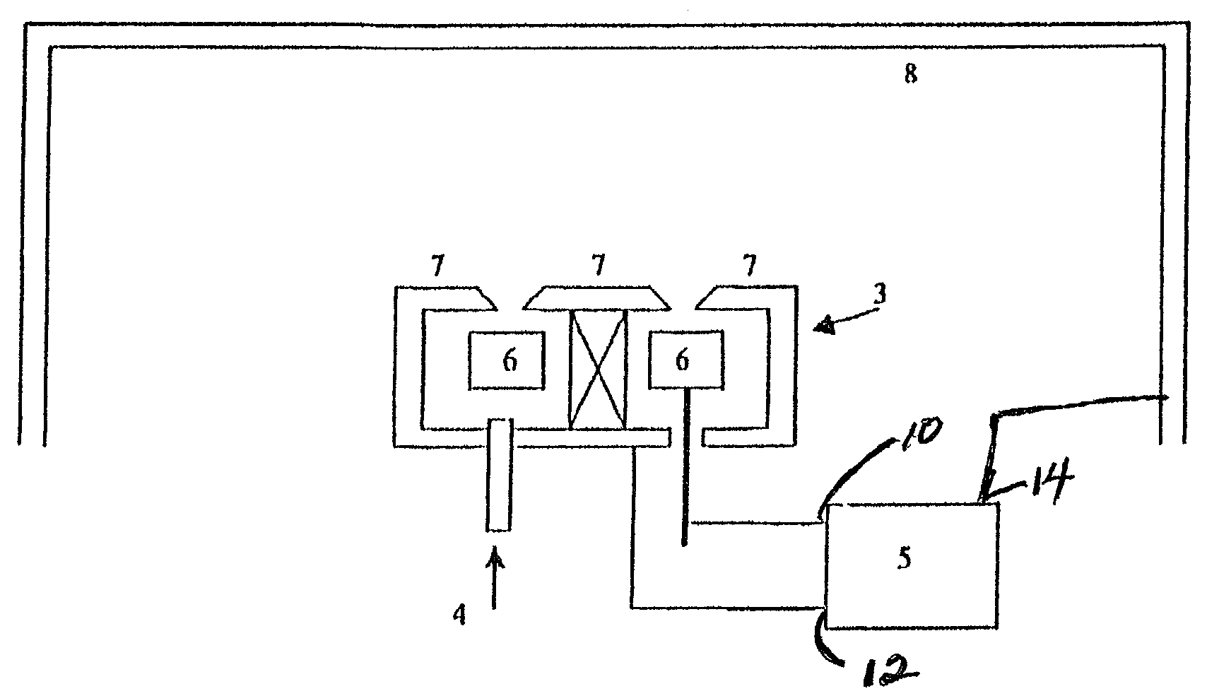
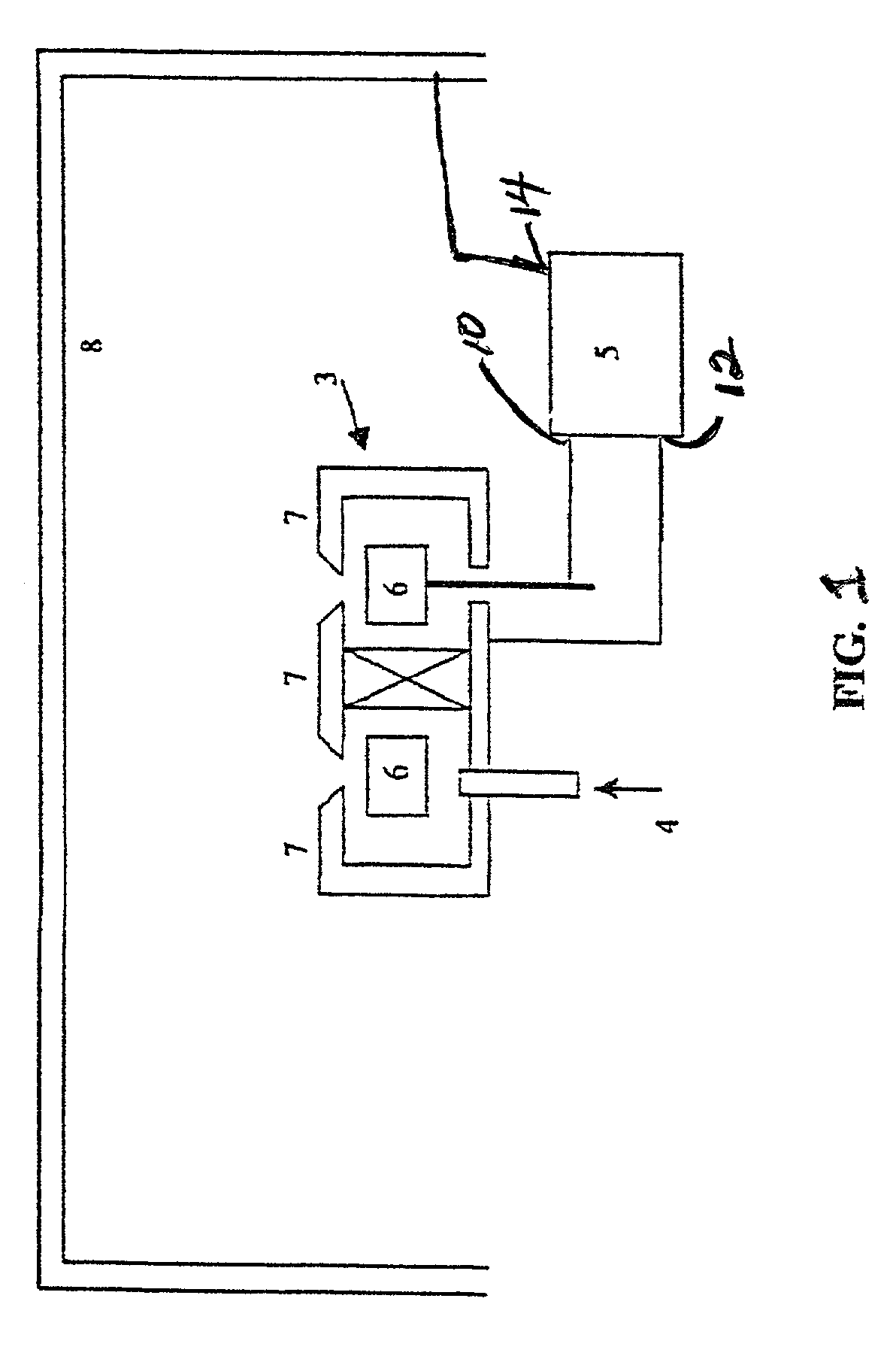
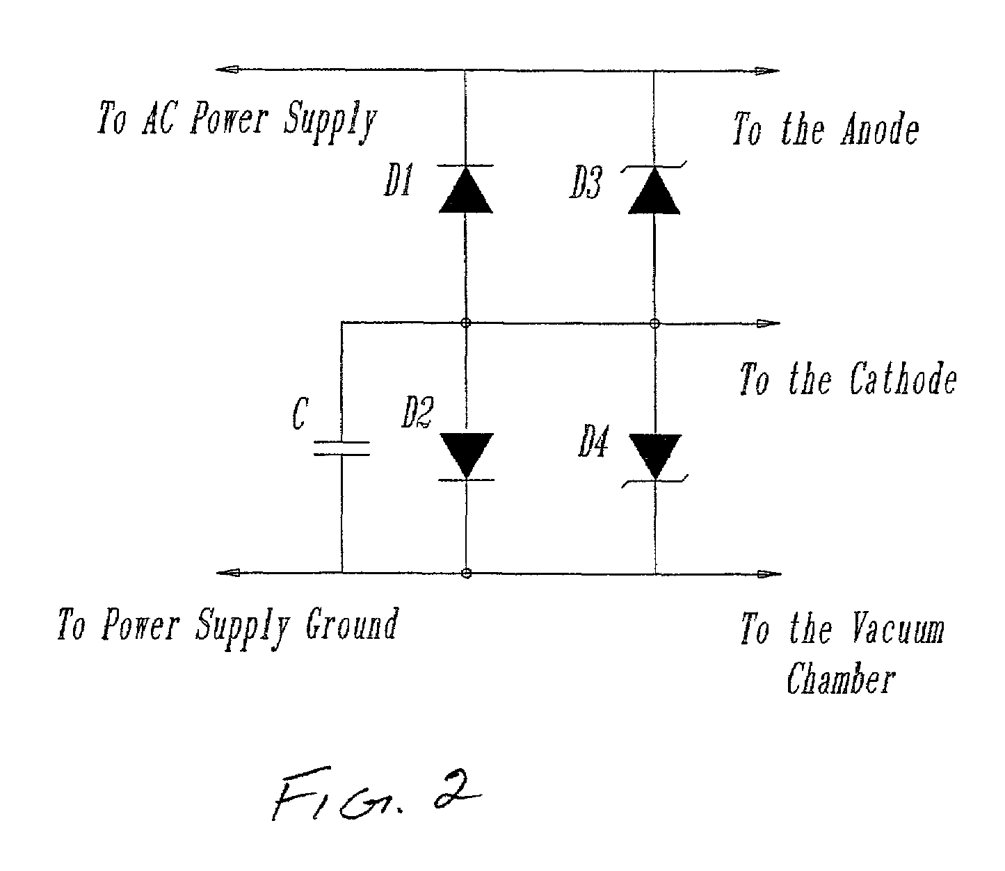
[0014]In one embodiment, the present invention uses the conductivity of a transient glow plasma that accompanies the ion beam in the vacuum chamber to neutralize positive electrical charge on a substrate and other apparatus surfaces. To accomplish that, a special ion source power supply is used that periodically reverses the polarity for a segment of time, biasing all or some parts of the ion source negatively relative to the substrate and the vacuum chamber. During this reverse bias cycle the plasma potential swings toward negative polarity and this can allow electrons from the plasma to reach surfaces that need to be neutralized.

[0015]Although relying upon fundamentally different principles, problems addressed in the field of magnetron sputtering can illustrate some of the advantages now available in the field of ion beam processing such as in closed drift ion sources, among others. In magnetron sputtering apparatus arcing was a severe problem that limited the throughput and reduc...


PUM

PropertyMeasurementUnit
frequencyaaaaaaaaaa
magnetic gapaaaaaaaaaa
voltageaaaaaaaaaa

Abstract

There is provided by this invention a unique ion source for depositing thin films on a substrate in a vacuum chamber that neutralizes the positive electric charges that develop on the substrate and vacuum chamber apparatus that may cause arcing and degradation of the film deposition. A power supply with a reversing voltage waveform is utilized that neutralizes the electric charge on the substrate and the vacuum chamber apparatus. A power supply applies an ac voltage to the anode of the ion source and a rectified ac voltage to the cathode. The ground terminal of the power supply is connected to the vacuum chamber. The rectifying circuit is comprised of zener diodes that clamp the voltage in the circuit from spikes during plasma ignition and a capacitor connected to negatively bias the cathode when there is no plasma discharge.

Description

BACKGROUND OF THE INVENTION[0001]1. Field of the Invention[0002]Generally, the invention pertains to the field of vacuum thin film deposition onto substrates using ion sources and modifying properties of substrates by ion beam treatment. Specifically, the invention focuses upon a new and improved method and apparatus for providing the supply of electrons onto a thin film substrate for neutralization of electric charge brought onto the surface of said substrate and other surfaces of the apparatus by the ion beam radiating from a closed drift ion source.[0003]2. Description of the Prior Art[0004]When a substrate is exposed to an ion beam, a need arises to close the electrical current path, or in another words to neutralize the electrical charge brought with the ions onto the substrate surface as well as onto other surfaces of the apparatus. This need is especially apparent for insulating substrates, but even conductive substrates as well as other surfaces of the apparatus frequently h...

Claims


Application Information

Patent Timeline
Patent Type & Authority Patents(United States)
IPC IPC(8): H01L21/306C23C14/00C23C16/00H01J7/24C23C16/50F03H1/00
CPCC23C16/50H01J27/143H01J37/026H01J37/08H01J2237/31
Inventor SHABALIN, ANDREWQUINN, COLINKISHINEVSKI, MICHAEL
Owner GENERAL PLASMA
Why Eureka
Try Eureka