

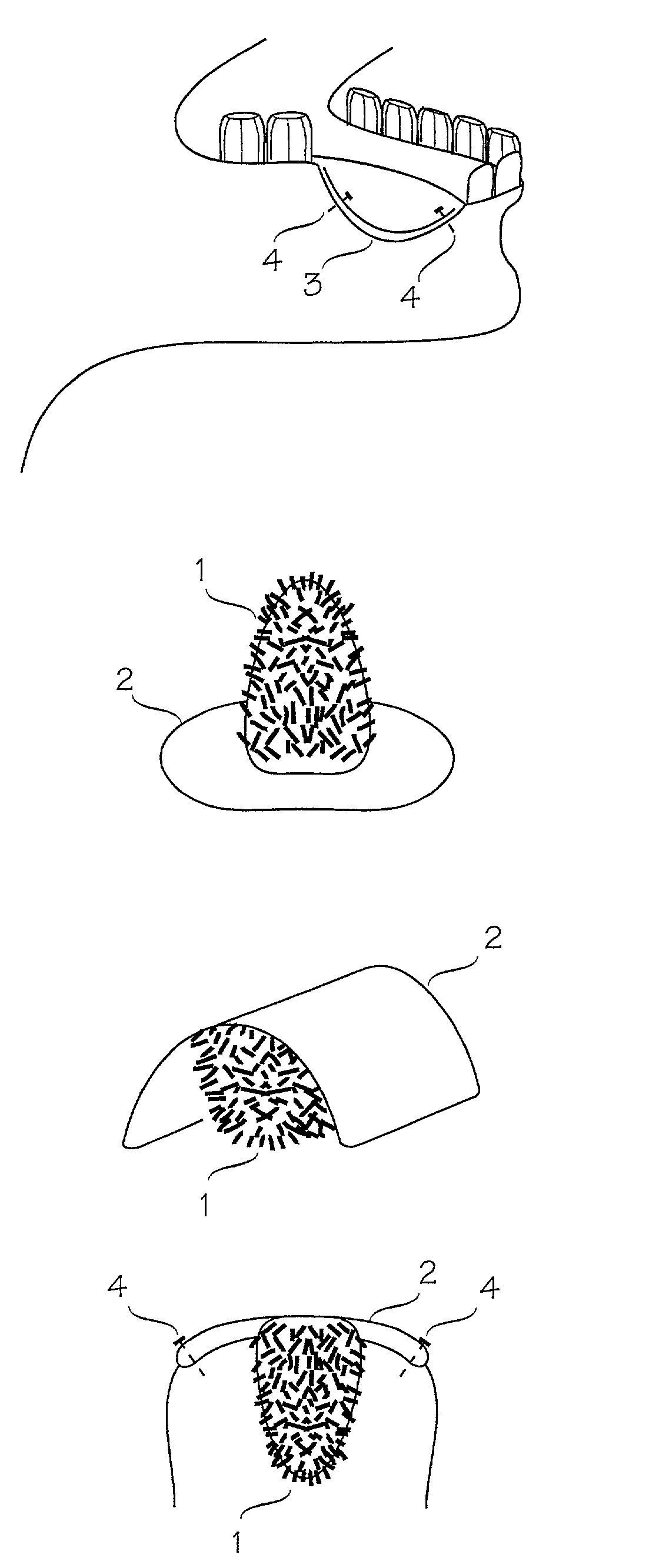
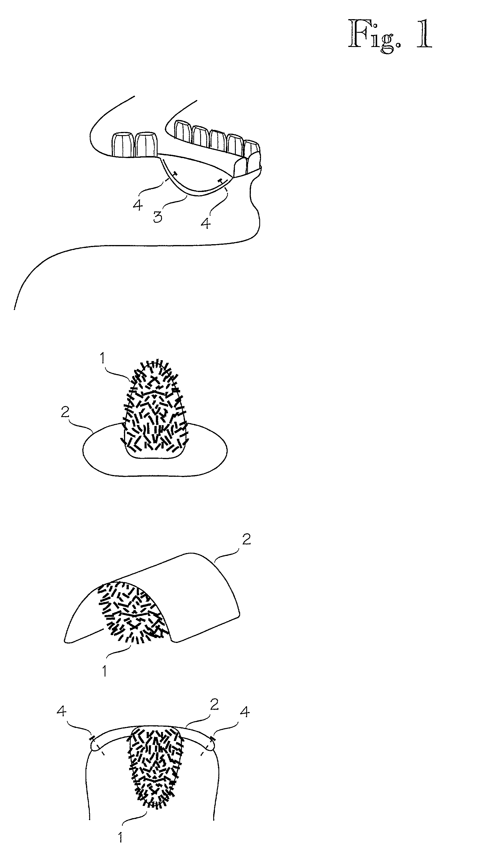
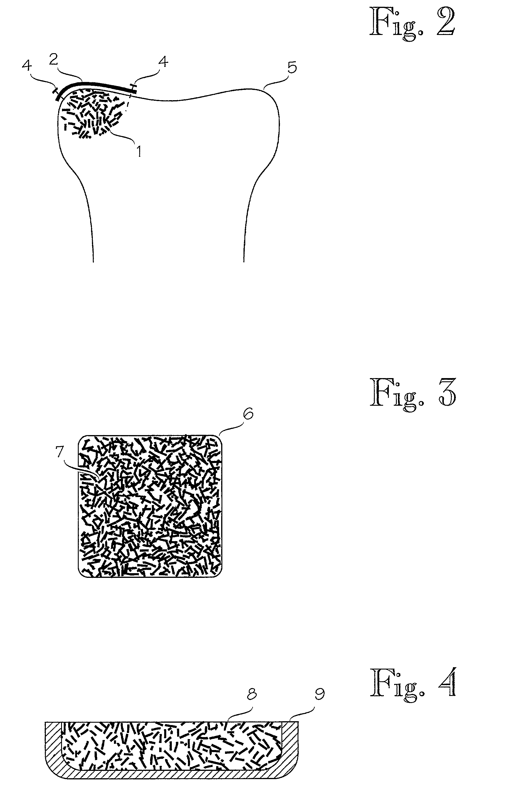
Bone grafting materials
a bone grafting and material technology, applied in the field of bone grafting materials, can solve the problems of troublesome procedures, additional pain for patients, and unrepaired bone tissue to be picked up, and achieve the effects of reducing pain, facilitating healing, and facilitating healing
- Summary
- Abstract
- Description
- Claims
- Application Information
AI Technical Summary
Benefits of technology
Problems solved by technology
Method used
Image

Examples
example 1
[0063]Bioactive glass fibers were formed from glass 13-93 (prepared by Abmin Technologies) by melt spinning. The piece of glass with mass of 150 g was placed into a platinum crucible, which had an orifice with diameter of 3.5 mm at the bottom. The crucible was then placed into the furnace (LINDBERG / BLUE CF56622C, by LINDBERG / BLUE, NC, U.S.A), which had opening at the bottom. Furnace was then heated up to a temperature of 960 C. As the glass melted it started to run from the orifice and it was drawn with a specially designed spinning roll. The speed of the roll was set to 200 mm / s. Obtained glass fiber was taken out from the roll. The diameter of the fiber was 0.175 mm (+ / −0.025 mm). Fibers were then chopped to a length of 10 mm (+ / −2 mm) by using scissors.
[0064]2 grams of the chopped fibers were placed on to a steel plate and the plate with glass fibers was placed into furnace. The furnace was slowly heated up to a temperature of 655° C. This was retained for 30 minutes and after th...
example 2
[0068]Bioactive glass fibers were formed from glass 13-93 by melt spinning as described in Example 1. The diameter of the fibers was 0.075 mm (+ / −0.025 mm).
[0069]Fibers were then chopped to the length of 15 mm (+ / −2 mm) by using scissors. Chopped fibers were placed on to a steel plate, and the plate with glass fibers was placed into a furnace. The furnace was slowly heated up to a temperature of 650° C. and the temperature was retained there for 30 minutes after which the furnace was cooled down.
[0070]From the obtained porous block three rectangular blocks were shaped with a surgical knife in order to measure porosity.
[0071]The outer dimensions and the weight of each block were measured. The calculated mean porosity of the blocks was 11 vol-% glass (+ / −7%) and 89 vol-% of air.
example 3
[0072]Bioactive glass fibers from glass 13-93 with diameter of 0.1 mm (+ / −0.03 mm) were formed by melt spinning as described in Example 1. Formed fibers were coated with viscous solution, which contained 5 grams of biodegradable polymer PLA (70L / 30DL) and 100 ml chloroform as a solvent. Fibers were coated as part of the spinning process (as described in Example 1) by dipping fibers into the solution prior to winding them up with spinning roll. The speed of the spinning roll was set to 200 mm / s.
[0073]Coated fibers were chopped by using scissors into a length of 15 mm (+ / −2 mm). Chopped fibers were placed on to a steel plate and the plate with glass fibers was placed in a furnace. The furnace was slowly heated to a temperature of 140° C. for 5 minutes after which the furnace was cooled down. The obtained body had porosity of approximately 15 vol-% glass, 2 vol-% of polymer and 82 vol-% of air. The body was slightly flexible and did not break when bent.
PUM
| Property | Measurement | Unit |
|---|---|---|
| temperature | aaaaa | aaaaa |
| temperature | aaaaa | aaaaa |
| temperature | aaaaa | aaaaa |
Abstract
Description
Claims
Application Information