Filtered cathodic arc deposition method and apparatus
- Summary
- Abstract
- Description
- Claims
- Application Information
AI Technical Summary
Benefits of technology
Problems solved by technology
Method used
Image
Examples
example 1
Filtered Arc Plasma Immersed Ion Cleaning
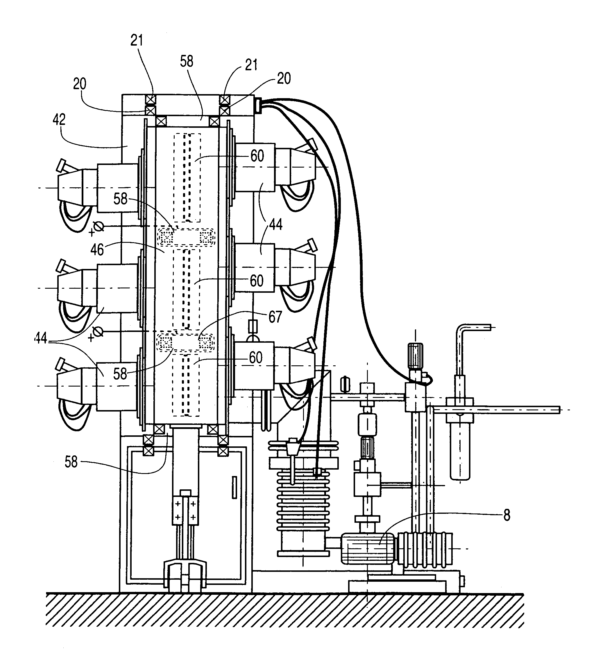
[0133]The arc coating apparatus shown in FIG. 3b was used in this process. The apparatus was equipped with two dual-filtered arc sources, having round cathodes 12 measuring 3″ in diameter and 2″ in height, one filtered arc source having titanium targets and the other having chromium targets. The exit opening of the filtered arc sources was equipped with load lock shutters 80a, 80b, electron-permeable to provide a free passage of electron current from the cathode targets 12 to distal auxiliary anodes 70 to thereby establish an auxiliary arc discharge. Augmented by the auxiliary arc discharge the ionization and activation of the gaseous component of the plasma environment in the coating chamber 42 was significantly increased (up to 30 to 40% in comparison with approximately 1 to 3% gas ionization rate without the auxiliary arc discharge).
[0134]2″ diameter, ¼″ thick HSS disc coupons as substrates 4 were washed in a detergent containing a water s...
example 2
Ion Nitriding and Ion Implantation in the Auxiliary Arc Discharge
[0135]The apparatus and substrate coupons 4 of Example 1 were used in this process. After the ion cleaning stage the gas mixture was changed to nitrogen as an ion nitriding gas, injected to create a total pressure ranging from 2×10⁻⁴ to 8×10⁻⁴ Torr. For ion nitriding the substrates 4 were preliminary heated to 300° C. to 450° C. using conventional heaters (not shown) installed in front of the distal auxiliary anodes 70 in the coating chamber 42. A self-bias voltage was established at a range from 100 to 400 volts. The current applied to distal auxiliary anodes 70 was set at 100 amps and the ion nitriding stage was performed for 1 hour.
[0136]For low-energy ion implantation the substrate temperature was set to a lower level, about 150 to 300° C., and the bias voltage ranged from 200 to 3000 volts. The ion implantation stage was performed for 1 hour.
[0137]The ion nitriding and ion implanted layers were characterized by st...
example 3
Auxiliary Arc Plasma Immersed Deposition of Chromium Nitride Filtered Arc PVD Coating
[0138]The apparatus of FIG. 3b was equipped with the same cathode targets 12 as in Example 1. The same substrate coupons 4 as in Example 1 were installed on the rotary satellites of substrate holder 2 with single rotation and preheated to 400° C. by conventional heaters installed in the coating chamber 42. After ion cleaning as described in Example 1 the lock load shutter 80b of the filtered arc source with the chromium cathode targets 12 was opened and the gas was changed to pure nitrogen with total pressure of 2×10⁻⁴ to 3×10⁻⁴ Torr. The deflecting and focusing magnetic coils 13, 20 of the filtered arc source magnetic systems were activated to deflect the chromium plasma stream toward substrates. The total current of the deflecting anode 50 was established at 50 amps, and the total current of the repelling anode was established at 40 amps. The current between chromium cathodes 12 and distal auxilia...
PUM
| Property | Measurement | Unit |
|---|---|---|
| Time | aaaaa | aaaaa |
| Flow rate | aaaaa | aaaaa |
| Magnetic field | aaaaa | aaaaa |
Abstract
Description
Claims
Application Information
 - R&D
- Intellectual Property
- Life Sciences
- Materials
- Tech Scout
- Unparalleled Data Quality
- Higher Quality Content
- 60% Fewer Hallucinations
Browse by: Latest US Patents, China's latest patents, Technical Efficacy Thesaurus, Application Domain, Technology Topic, Popular Technical Reports.
© 2025 PatSnap. All rights reserved.Legal|Privacy policy|Modern Slavery Act Transparency Statement|Sitemap|About US| Contact US: help@patsnap.com


