Systems and methods for electrosurgery

a technology of electrosurgery and system, applied in the field of electrosurgery, can solve the problems of disc shock absorption, nerve root pinching, back and leg pain, etc., and achieve the effects of preventing clogging of the lumen, facilitating tissue removal, and facilitating tissue ablation or contraction

Inactive Publication Date: 2007-09-18
ARTHROCARE
View PDF395 Cites 337 Cited by
  • Summary
  • Abstract
  • Description
  • Claims
  • Application Information

AI Technical Summary

Benefits of technology

[0018]In procedures requiring ablation of tissue, the tissue is removed by molecular dissociation or disintegration processes. In these embodiments, the high frequency voltage applied to the active electrode(s) is sufficient to vaporize an electrically conductive fluid (e.g., gel or saline) between the active electrode(s) and the tissue. Within the vaporized fluid an ionized plasma is formed, and charged particles (e.g., electrons) cause the molecular breakdown or disintegration of several cell layers of the tissue. This molecular dissociation is accompanied by the volumetric removal of the tissue. This process can be precisely controlled to effect the volumetric removal of tissue as thin as 10 microns to 150 microns with minimal heating of, or damage to, surrounding or underlying tissue structures. A more complete description of this phenomenon is described in commonly assigned U.S. Pat. No. 5,683,366, the complete disclosure of which is incorporated herein by reference.
[0019]In another aspect of the invention, the present invention is useful for performing spinal surgery. The method comprises positioning an electrosurgical instrument in close proximity to an intervertebral disc. An electrically conductive fluid is delivered toward a distal tip of the electrosurgical instrument. A high frequency electrical energy is applied to the active electrode such that the conductive fluid completes a current flow path between the active electrode and a return electrode. The conductive fluid is aspirated through an aspiration lumen positioned proximal of the return electrode. Because the aspiration lumen is positioned away from the fluid delivery lumen and proximal of the return electrode, a plasma can be aggressively created and the tissue can be ablated or contracted more efficiently.
[0020]The tissue may be completely ablated in situ with the mechanisms described above, or the tissue may be partially ablated and partially resected and aspirated from this operating corridor. In a preferred configuration, the probe will include one or more aspiration electrode(s) at or near the distal opening of an aspiration lumen. In this embodiment, high frequency voltage is applied between the aspiration electrode(s) an

Problems solved by technology

This results in a weakening of the shock absorption properties of the disc and a narrowing of the nerve openings in the sides of the spine which may lead to pinching of the nerve root.
This disc degeneration can cause back and leg pain.
The mere proximity of the nucleus pulposus or a damaged annulus to a nerve can cause direct pressure against the nerve, resulting in pain and sensory and motor deficit.
In some cases, the disc tissue is irreparably damaged, thereby necessitating removal of a portion of the disc or the entire disc to eliminate the source of inflammation and pressure.
In addition, the risk of instability from ligament and bone removal is generally lower in endoscopic procedures than with open discectomy.
Unfortunately, these mechanical instruments greatly lengthen and increase the complexity of the procedure.
In addition, these instruments might sever blood vessels within this tissue, usually causing profuse bleeding that obstructs the surgeon's view of the target site.
In addition to the abov

Method used


Image

  • Systems and methods for electrosurgery
  • Systems and methods for electrosurgery
  • Systems and methods for electrosurgery

Examples


Embodiment Construction

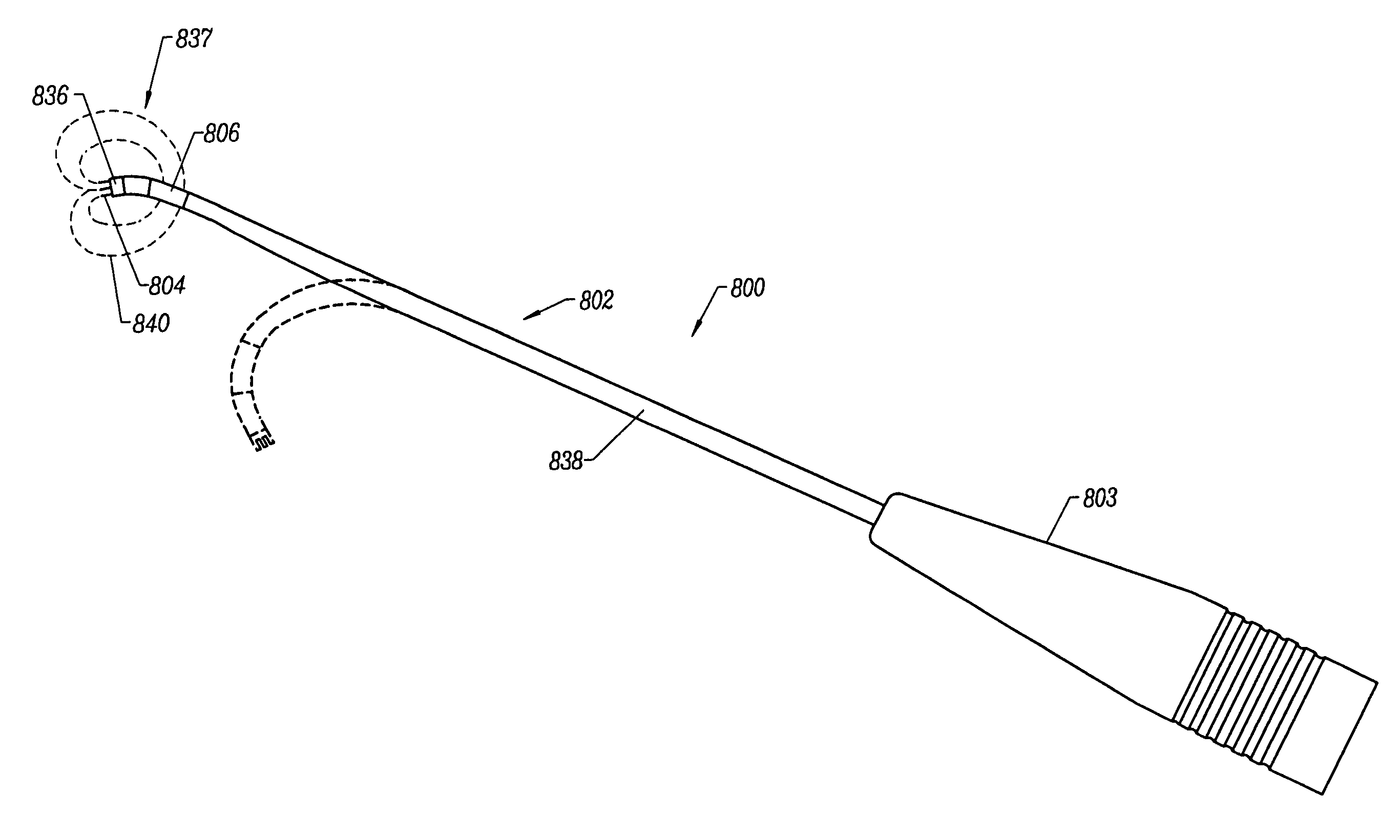
[0102]The present invention provides systems and methods for selectively applying electrical energy to a target location within or on a patient's body, particularly including tissue or other body structures in the spine. These procedures include laminectomy / disketomy procedures for treating herniated disks, decompressive laminectomy for stenosis in the lumbosacral and cervical spine, medial facetectomy, posterior lumbosacral and cervical spine fusions, treatment of scoliosis associated with vertebral disease, foraminotomies to remove the roof of the intervertebral foramina to relieve nerve root compression and cervical and lumbar diskectomies, shrinkage of vertebral support tissue, and the like. These procedures may be performed through open procedures, or using minimally invasive techniques, such as thoracoscopy, arthroscopy, laparascopy or the like.

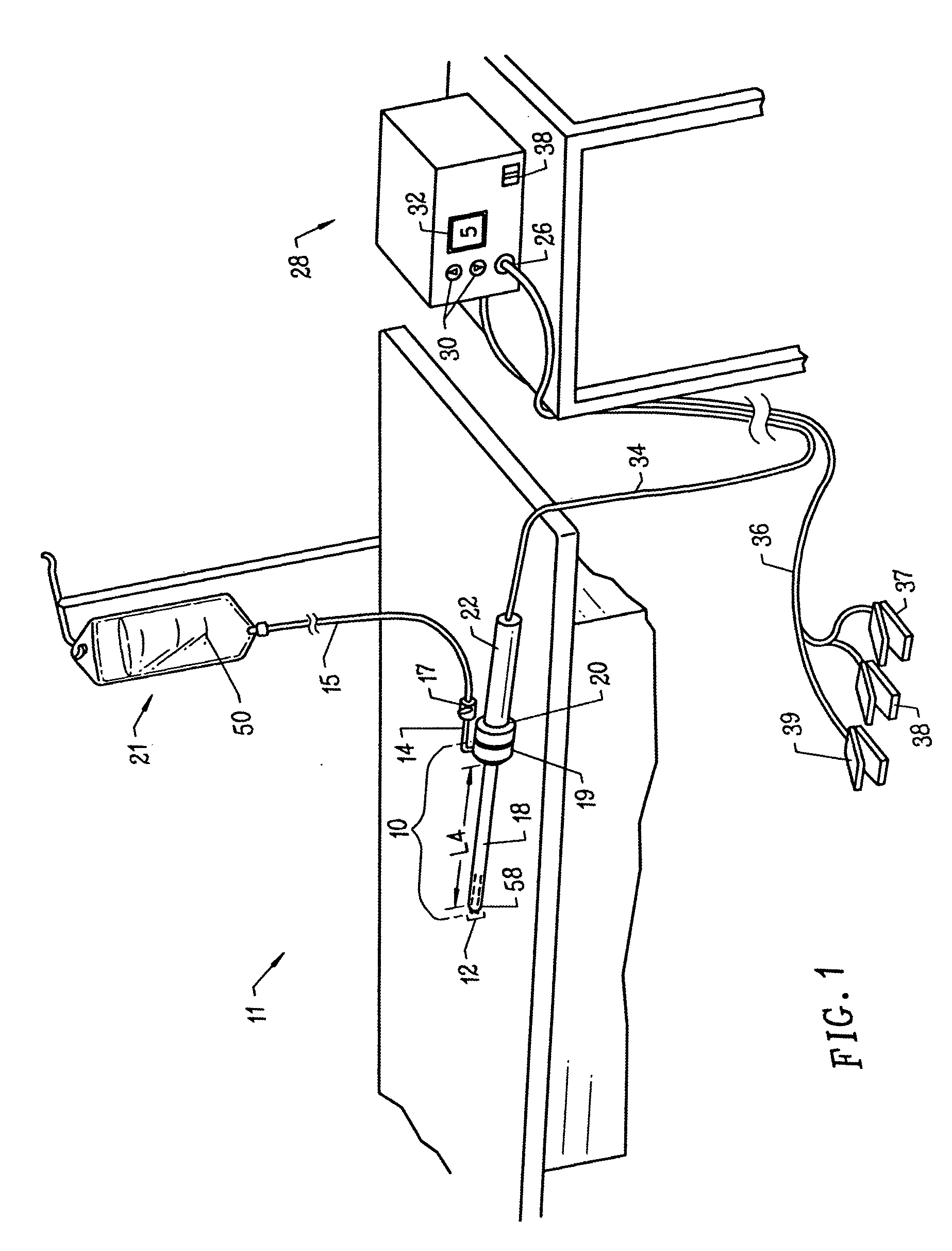
[0103]In the present invention, high frequency (RF) electrical energy is applied to one or more active electrodes in the presence of e...


PUM

PropertyMeasurementUnit
Temperatureaaaaaaaaaa
Angleaaaaaaaaaa
Electrical conductivityaaaaaaaaaa

Abstract

Methods and apparatus for selectively applying electrical energy to a target location within a patient's body, particularly including tissue in the spine. In a method of the invention high frequency (RF) electrical energy is applied to one or more active electrodes on an electrosurgical probe in the presence of an electrically conductive fluid to remove, contract or otherwise modify the structure of tissue targeted for treatment. In one aspect, a dura mater and spinal cord are insulated from the electrical energy by an insulator positioned on a non-active side of the probe. In another aspect, a plasma is aggressively formed in the electrically conductive fluid by delivering a conductive fluid to a distal end portion of the probe and aspirating the fluid from a location proximal of the return electrode. In another aspect, a distal end of an electrosurgical probe having at least one electrode on a biased, curved, bent, or steerable shaft is guided or steered to a target site within an intervertebral disc having a disc defect for treatment of tissue to be treated at the target site by the selective application of electrical energy thereto.

Description

RELATED APPLICATIONS[0001]This application is a divisional of U.S. patent application Ser. No. 09 / 708,962 filed Nov. 8, 2000, now U.S. Pat. No. 6,726,684, which claims the benefit of Provisional Patent Application No. 60 / 204,206 filed May 12, 2000, and is a continuation-in-part of U.S. patent application Ser. No. 09 / 676,194, entitled “Methods for Repairing Damaged Intervertebral Discs”, filed Sep. 28, 2000, now U.S. Pat. No. 6,602,248.[0002]The present invention is related to commonly assigned co-pending Provisional Patent Application Nos. 60 / 062,996 and 60 / 062,997, non-provisional U.S. patent application Ser. No. 08 / 970,239 entitled “Electrosurgical Systems and Methods for Treating the Spine,” filed Nov. 14, 1997, and Ser. No. 08 / 977,845 entitled “Systems and Methods for Electrosurgical Dermatological Treatment,” filed on Nov. 25, 1997, U.S. application Ser. No. 08 / 753,227, filed on Nov. 22, 1996, and PCT International Application, U.S. National Phase Serial No. PCT / US94 / 05168, fil...

Claims


Application Information

Patent Timeline
IPC IPC(8): A61B18/14A61B17/00A61B18/00A61B19/00
CPCA61B18/148A61B18/1482A61B18/1485A61B18/149A61B18/1206A61B18/14A61B18/1477A61B18/1492A61B19/201A61B2017/00261A61B2018/00119A61B2018/0016A61B2018/00291A61B2018/00327A61B2018/00392A61B2018/00434A61B2018/0044A61B2018/00577A61B2018/00583A61B2018/00589A61B2018/00702A61B2018/00791A61B2018/00827A61B2018/00982A61B2018/1213A61B2018/124A61B2018/1253A61B2018/1273A61B2018/1425A61B2018/1467A61B2018/1472A61B2018/162A61B2018/165A61B2218/002A61B18/042A61B90/11
Inventor WOLOSZKO, JEANHOVDA, DAVID C.THAPLIYAL, HIRA V.EGGERS, PHILIP E.
Owner ARTHROCARE
Why Eureka
Try Eureka