Tin-silver-copper plating solution, plating film containing the same, and method for forming the plating film

a technology of silver-copper and plating solution, which is applied in the direction of manufacturing tools, welding/cutting media/materials, and manufacturing tools, etc., can solve the problems of difficult control of silver-ion concentration in tin-silver-copper plating solution, and achieve the effect of reducing heating temperature at the time of mounting, high joining strength and securement of desired conductivity

Inactive Publication Date: 2007-09-25
SHINRYOI CORP
View PDF17 Cites 27 Cited by
  • Summary
  • Abstract
  • Description
  • Claims
  • Application Information

AI Technical Summary

Benefits of technology

[0011]A tin-silver-copper plating solution according to a first invention for attaining the above objects comprises water which is a primary medium, a sulfonic acid, tin ions, copper ions and silver ions, wherein a concentration of the silver ions is 0.01 to 0.1 mol / L (liter). Generally, controlling the silver-ion concentration in the tin-silver-copper plating solution is very difficult. The tin-silver-copper plating solution according to the first invention has the silver-ion concentration in a range of 0.01 to 0.1 mol / L and concentrations of the tin and copper ions are determined based on the silver-ion concentration. In this manner, obtained is the tin-silver-copper plating solution with less solid precipitations and better storage stability over a long time without causing quality deterioration even when a plating process is performed continuously in a large amount.
[0012]In this case, the tin-silver-copper plating solution of the first invention preferably has the concentrations of the tin ions in a range of 0.21 to 2 mol / L and of the copper ions in a range of 0.002 to 0.02 mol / L. Moreover, it is preferable to set a mole ratio of the silver-ion concentration to the copper-ion concentration in a range of 4.5 to 5.58. Here, it is possible to perform plating with a tin-silver-copper alloy having a lower melting point efficiently (namely, with high productivity) by determining the respective metal-ion concentrations within the above ranges. In addition, it is more preferable to set the concentrations of the tin ions, silver ions and copper ions in ranges of 0.3 to 1 mol / L, 0.02 to 0.05 mol / L and 0.003 to 0.01 mol / L, respectively. It is further preferable to set the ratio (mole ratio) of silver-ion concentration to the copper-ion concentration in a range of 4.5 to 5.5. As a result, tin-silver-copper alloy plating with a lower melting point can be performed.

Problems solved by technology

Generally, controlling the silver-ion concentration in the tin-silver-copper plating solution is very difficult.

Method used


Image

  • Tin-silver-copper plating solution, plating film containing the same, and method for forming the plating film
  • Tin-silver-copper plating solution, plating film containing the same, and method for forming the plating film
  • Tin-silver-copper plating solution, plating film containing the same, and method for forming the plating film

Examples


experimental examples

[0114]Hereinafter, the present invention will be described more specifically with reference to experimental examples. The scope of the present invention is not limited to the experimental examples as long as it does not exceed the gist of the invention.

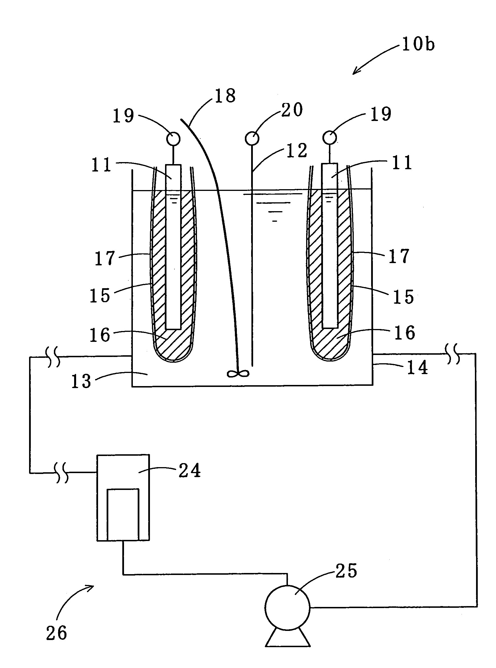
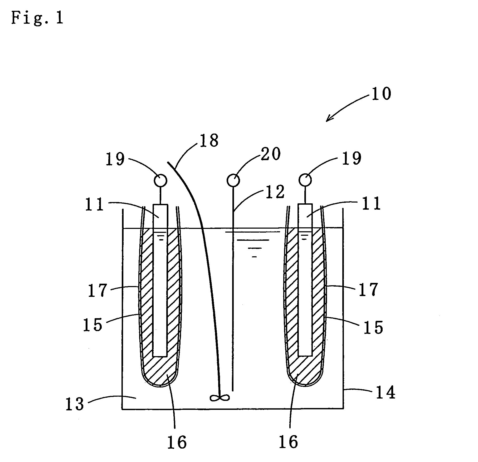
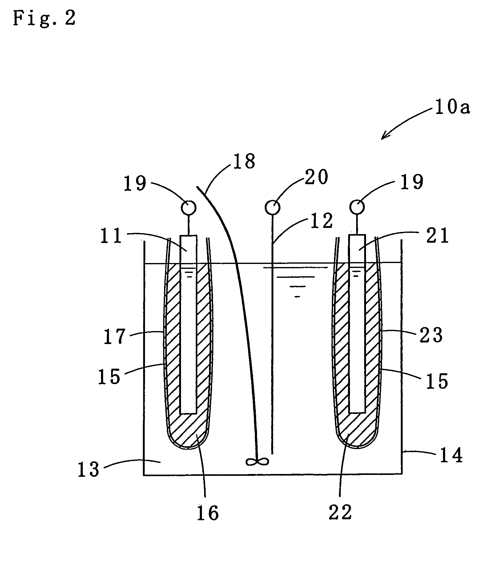
[0115]In order to observe effects of the plating solution, the electrolytic plating method, the plating film and the soldering method in accordance with the present invention, experiments were carried out to measure metal content ratios, finished appearances and melting points of the plating films plated by the electrolytic plating method of the present invention using the plating solution of the present invention. Further, experiments were carried out to measure joining strength and solder wettability of the plating films on test pieces soldered by applying the reflow soldering system according to one embodiment of the present invention.

[0116]The tin-silver-copper plating solution according to one embodiment of the present invention ...

experimental example

“1b”

[0139]Plating was carried out in the same way as that in the experimental example “1a” except the 42-alloy test-piece with an area of 0.3 dm2 was replaced with a copper test-piece with an area of 0.3 dm2.

[0140]The results are shown in the experimental example “1b” in Table 4. Contents of copper and silver in the plating film were not measured. However, the plating film was estimated to have approximately the same composition as that measured in the experimental example “1a”.

[0141]Each result of the tests was approximately the same as that in the experimental example “1a” except a great improvement in the joining strength of the test-piece with the copper-coated testing board made from glass epoxy. Also, the appearance was acceptable and the melting point became lower.

experimental example 2

[0142]Plating was carried out in the same way as that in the experimental example “1a” except the density of current with a direct-current waveform was 5.0 A / dm2. Even when the plating was carried out with the changed current density, a surface shape observed with an electron microscope was nearly the same as that in the experimental example “1a”. Also, the surface shape was smooth, and particles of the surface were uniform-sized without fluctuation.


PUM

PropertyMeasurementUnit
thicknessaaaaaaaaaa
pore diameteraaaaaaaaaa
current densityaaaaaaaaaa

Abstract

An electrolytic plating method, including: preparing a plating solution including water which is a primary medium, a sulfonic acid, and tin, copper, and silver ions, and a complexing agent, concentrations of the sulfonic acid, and tin, copper, and silver ions being 0.5 to 5 mol / L, 0.21 to 2 mol / L, 0.002 to 0.02 mol / L, and 0.01 to 0.1 mol / L, respectively, a mole ratio of the silver-ion concentration to the copper-ion concentration being in a range of 4.5 to 5.58; and separating a solution around a soluble anode containing 90 percent or more of tin from the plating solution on a cathode side by a non-ionic micro-porous membrane having a pore diameter of 0.01 to 0.05 μm and a thickness of 5 to 100 μm.

Description

[0001]This application is a continuation of PCT / JP03 / 09351 filed on Jul. 23, 2003.TECHNICAL FIELD[0002]The present invention relates to a tin-silver-copper plating solution used for a lead-free solder plating, a plating method using the same, and a plating film and a soldering method thereof.BACKGROUND ART[0003]Conventionally, tin plating or tin-lead alloy plating has been performed on components to be soldered, for instance components which constitute electronic equipment such as chip parts, crystal oscillators, bumps, connector pins, lead frames, various hoop materials, lead pins of packages and circuits of printed boards. The pure tin plating has problems such as deterioration in solderability and occurrence of whisker-shaped crystals (whiskers) on a film. Furthermore, the use of lead has recently been reduced from a standpoint of environmental protection; thus, lead-free plating has become desirable.[0004]As the lead-free plating, for example, a tin-silver alloy, a tin-bismuth a...

Claims


Application Information

Patent Timeline
Patent Type & Authority Patents(United States)
IPC IPC(8): C25D3/58C25D3/60B23K35/26C25D5/00C25D5/18C25D17/10C25D21/06C25D21/18H01L23/495H05K3/34
CPCB23K35/262C25D3/60C25D5/18C25D17/10C25D21/06C25D21/18C25D17/002C25D17/16C25D5/003H01L23/49582H05K3/3463H05K3/3473H01L2924/0002H01L2924/00C25D5/611C25D5/627
Inventor SONODA, HIROMINAKAMURA, KATSUJI
Owner SHINRYOI CORP
Why Eureka
Try Eureka