Composites pressure resin infusion system (ComPRIS)

a pressure resin and composite material technology, applied in the direction of synthetic resin layered products, weaving, transportation and packaging, etc., can solve the problems of inability to achieve the effect of infusing frp composite laminates and hybrid composite parts with different substrates based on the distribution media, and affecting the quality of composite parts. , to achieve the effect of improving the quality of composite parts, and improving the fracture toughness of the interfa

Inactive Publication Date: 2007-11-27
MAINE UNIV OF
View PDF9 Cites 18 Cited by
  • Summary
  • Abstract
  • Description
  • Claims
  • Application Information

AI Technical Summary

Benefits of technology

[0014]An interphase is a functionally graded region of bonding, and for the remainder of this document the term ‘interphase’ refers to the bondline created by the ComPRIS process including both interface and true interphase bonds. Generally speaking, ‘interphase’ refers to a “3-dimensional bondline”, while ‘interface’ refers to a “2-dimensional bondline”. The extent of the bondline in the third dimension (created by the ComPRIS process) will depend upon the permeability of the article substrates. The 3-dimensional bondline created by permeation of the resin into one or more components of the composite article results in a functionally graded material of high quality without vacuum induced defects including microvoids. It results in penetration of the resin into the fiber reinforcement layers, furnish or laminates, as well as into the adjacent substrate or core material to provide a gradual transition between the two dissimilar materials, thus greatly improving fracture toughness of the interface compared to current fabrication processes with abrupt “glue-line” interfaces, in which the resin essentially does not permeate either of two facing components of the comp

Problems solved by technology

However, the VARTM process requires two stiff molds to produce composite laminates.
Since, the maximum vacuum that can be applied in the SCRIMP™ process is approximately 1 Atmosphere (30 in of Hg or −15 psi), the ability of the technique to infuse FRP composite laminates and hybrid composite parts with different substrates is limited based on the distribution media.
Furthermore, since the SCRIMP™ process requires dedicated labor to properly set up the distribution media and seal the vacuum bag avoiding gas leaks, it is relatively slow and expensive for mass production of composite parts.
The article or part is not consolidated to allow better resin infiltration into the fabric of the FRP.
Higher clamping or consolidation pressures applied were said to reduce performance o

Method used


Image

  • Composites pressure resin infusion system (ComPRIS)
  • Composites pressure resin infusion system (ComPRIS)
  • Composites pressure resin infusion system (ComPRIS)

Examples


example 1

[0150]The purpose of this study was to investigate procedures (in billet production and fabrication) that may influence the integrity and accelerated durability of the bondlines of ComPRIS specimens. After production of standard billets or articles, these were assessed in accordance with a standard cyclic delamination test (ASTM D1101 as a preliminary screening test for later work with ASTM D2559)

[0151]One of the long-term goals for the development of the ComPRIS process includes the production of laminated beams and FRP composite bonded laminated beams. As such, wood-to-wood fabrication was studied as well as FRP composite to wood bonding using E-glass unidirectional fibers sandwiched between layers of wood.

[0152]Testing was performed in accordance with ASTM D1101 (Integrity of Adhesive Joints in Structural Laminated Wood Products for Exterior Use). This ASTM standard test is an accelerated aging method used for the screening of materials in preliminary studies.

1.1 Procedures

[0153]...

example 2

[0186]2.1 Procedure

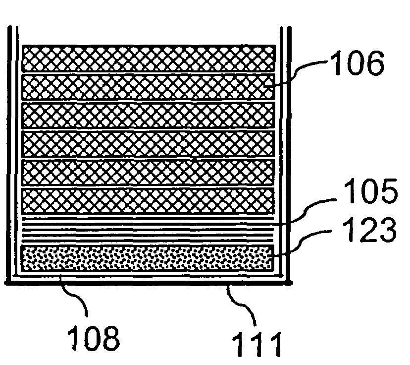
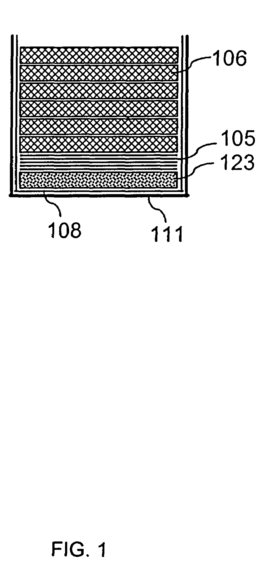
[0187]Billets of 10 laminates of unidirectional E-glass fabric (VEW 260 from BTI-Saint Gobain) placed in between the southern yellow pine lumber, were fabricated as described in Example 1 for ComPRIS production. A vinyl ester resin (Derakane 411-C50) was used in all tests. For all tests, the resin was mixed with a 2% (by weight) catalyst (2-Butanone peroxide, manufactured by Aldrich Chemical Corporation).

[0188]The boards used were 1″×6″ (nominal), and measured 24″ in length. Billets were also fabricated using the same materials but using the SCRIMP™ process for comparative purposes in later testing. From both the ComPRIS and SCRIMP™ billets, small cross sections of material were cut and these sections were prepared for viewing using electron microprobe analysis. A model Cameca SX100 Electron microprobe unit was used with an accelerating voltage of 15 kV and 10 nanoamps in the backscatter mode. Images were captured digitally to allow a comparative examination of th...

example 3

[0193]3.1 Procedure

[0194]Billets comprised of two layers of polyester / polyethylene panels material sandwiched around 10 layers of unidirectional E-glass fabric (VEW 260 from BTI-Saint Gobain) were produced using the ComPRIS process as described above in Examples 1 and 2. In this work however, one of the panels, being of wood plastic lumber (an impermeable material), were ripped to a depth of 5 mm on one face by making 3 equally distant saw kerfs along the length of the material. These kerfed faces were positioned to interface with the fabric layers, to relieve the build up of entrapped gas within the samples during ComPRIS fabrication. A vinyl ester resin (Derakane 411-C50) was used in all tests. For all tests, the resin was mixed with a 2% (by weight) catalyst (2-Butanone peroxide, manufactured by Aldrich Chemical Corporation).

[0195]After curing under pressure, the billets were removed, sectioned along their length by ripping a thin central strip from the length of each billet. The...


PUM

PropertyMeasurementUnit
Fractionaaaaaaaaaa
Fractionaaaaaaaaaa
Pressureaaaaaaaaaa

Abstract

The present invention provides resin infused composite articles. Also provided is a method for preparing the composite articles of the invention. The method includes infusing the assembled components of the composite with resin under pressure. There are also provided numerous devices of varying configuration that are of use in the methods of the invention.

Description

BACKGROUND OF THE INVENTION[0001]Current resin transfer molding (RTM) processes are used to produce Fiber Reinforced Polymer (FRP) composite materials by infusing resins into different types of fiber reinforcement (Beckwith and Hyland, “Resin transfer molding: A decade of technology advances”, SAMPE Journal, Vol. 34, No. 6, November-December, pp. 7-19 (1998)). RTM methods are characterized by resin infusion of fiber reinforcement, fabrics or preforms within a closed mold or tool. RTM methods have the advantage of minimizing void content, producing high fiber volume content and controlling volatile organic compound (VOC) emissions. Resin infusion is attained by a pressure gradient that can be developed in three different ways: 1) by vacuum; 2) by external pressure and / or gravity; and 3) by a combination of vacuum and pressure.[0002]Among the family of RTM processes, the subset known as Vacuum Assisted Resin Transfer Molding (VARTM) has shown great potential for fabricating FRP compos...

Claims


Application Information

Patent Timeline
IPC IPC(8): B32B5/26B32B27/04B32B27/40B32B9/04B29C70/08B29C70/44B29C70/46B29C70/54B32B5/28
CPCB29C70/088B29C70/44B32B27/04B29C70/546B32B5/28B29C70/467Y10T442/3496Y10T428/31573Y10T442/3797Y10T442/30Y10T428/31504B32B2262/101B32B21/10B32B5/12B32B5/24B32B2260/021B32B2260/046
Inventor GOODELL, BARRY S.LOPEZ-ANIDO, ROBERTO A.HERZOG, BENJAMIN
Owner MAINE UNIV OF
Why Eureka
Try Eureka