Switching power supply in an integrated circuit having a comparator with two threshold values, a synchronization input and output, voltage feedback and efficient current sensing

a technology of integrated circuits and power supply devices, which is applied in the direction of instruments, ignition automatic control, process and machine control, etc., can solve the problems of electronic devices incurring an increase in current consumed, the ripple of output voltage increases, and the switching frequency changes, so as to reduce the change in output voltage, reduce the ripple of output voltage at the light load, and improve the power conversion efficiency

Active Publication Date: 2008-01-01
RENESAS ELECTRONICS CORP
View PDF32 Cites 42 Cited by
  • Summary
  • Abstract
  • Description
  • Claims
  • Application Information

AI Technical Summary

Benefits of technology

[0013]Since such a switching power supply device is not provided with the sense resistor which is connected in series with the coil and through which the current flowing into the coil is caused to flow, a power loss can be reduced. Since the error amplifier becomes unnecessary, the characteristic of response to each of a change in input voltage and a change in output voltage is improved. The provision of the phase compensating circuit becomes unnecessary and hence a circuit scale can be reduced correspondingly. Further, the switching frequency does not depend on manufacture variations in coil's inductance, variations in temperature, the magnitude of a current that flows through the coil, etc. and hence the ripple of the output voltage can be reduced.
[0018]Only a series regulator is automatically operated upon a light load without providing a peculiar switching control circuit. Thus, a ripple voltage at the light load is low and power conversion efficiency can be improved. Since a drive frequency continuously changes according to a load current upon switching between the operation and stop of switching of a switching regulator, a switching power supply circuit is capable of reducing a change in output voltage at the switching between the operation and stop of switching thereof.
[0019]Alternatively, since the setting of an external sync clock frequency to greater than or equal to an audio frequency by an external sync input control circuit enables prevention of a drive frequency from being reduced to the audio frequency or less, the frequency can be set so as not to fall into an audio frequency band while high efficiency and a low ripple voltage are being maintained in a wide range from a light load to a heavy load. It is also possible to perform a parallel redundancy operation without the need for a complicated circuit used for carrying out load sharing. Executing phase shifting makes it possible to carry out even low rippling of an input / output voltage together.

Problems solved by technology

Fourthly, a problem arises in that when a current I1 that flows through the coil is small, an output current Ierr of the error amplifier becomes innegligible so that (I1−Ierr)·Rcs≈I1Rcs corresponding to the condition that the equation (1) is established is not established, thereby causing a change in switching frequency, and since the monitor voltage cannot exceed the hysteresis voltage of the comparator, the switching frequency is not fixed and hence the ripple of the output voltage increases.
In recent years, however, an electronic apparatus incurs an increase in the current consumed by the LSI (Large Scale Integration) with the high function and high-speed operation as described above, whereas an electronic apparatus such as a portable device with a battery as a power supply needs to prolong the life of the battery.
Furthermore, the operating voltage of the LSI tends to decrease with the advance of miniaturization of the LSI.
As a result, there is a possibility that when the output voltage falls short of the lowest operating voltage of the LSI, the LSI will malfunction.

Method used


Image

  • Switching power supply in an integrated circuit having a comparator with two threshold values, a synchronization input and output, voltage feedback and efficient current sensing
  • Switching power supply in an integrated circuit having a comparator with two threshold values, a synchronization input and output, voltage feedback and efficient current sensing
  • Switching power supply in an integrated circuit having a comparator with two threshold values, a synchronization input and output, voltage feedback and efficient current sensing

Examples


Embodiment Construction

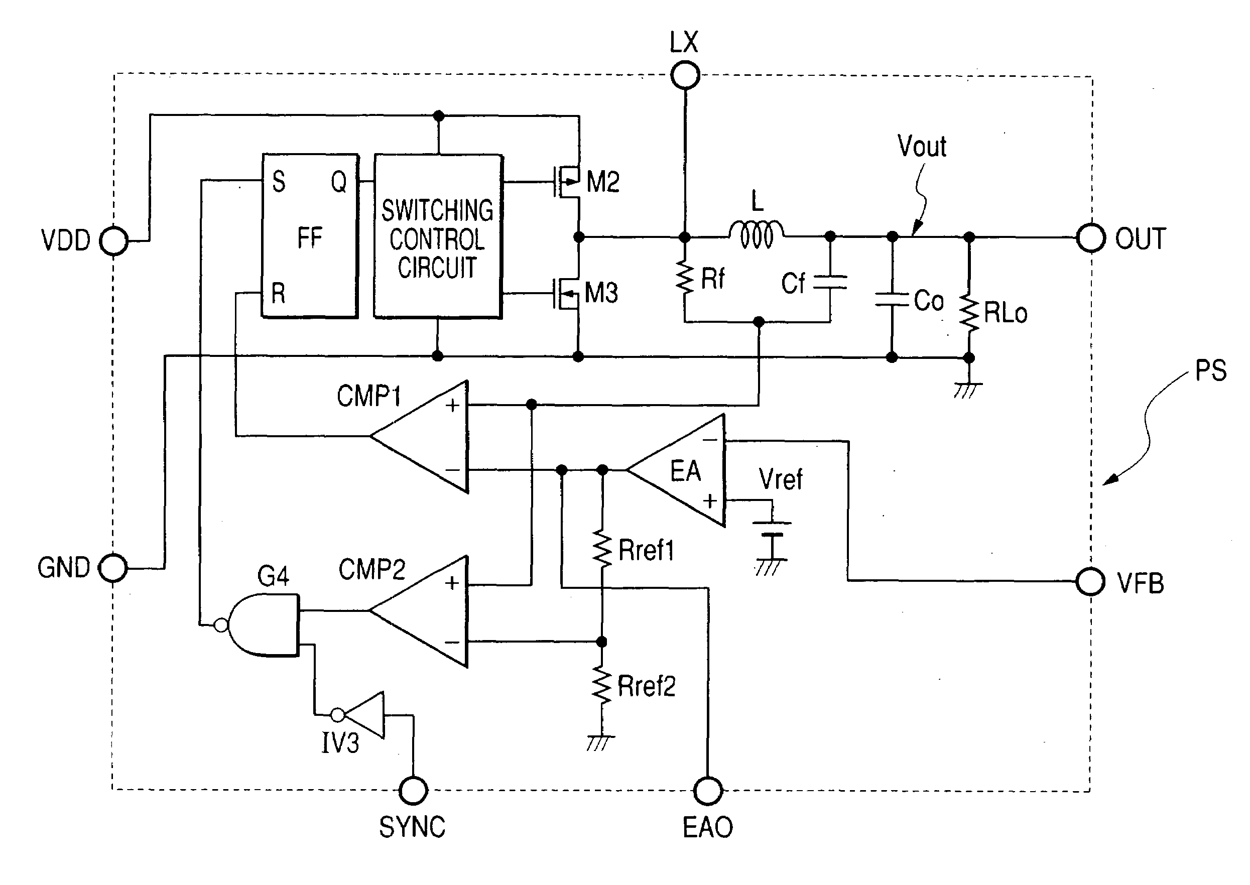
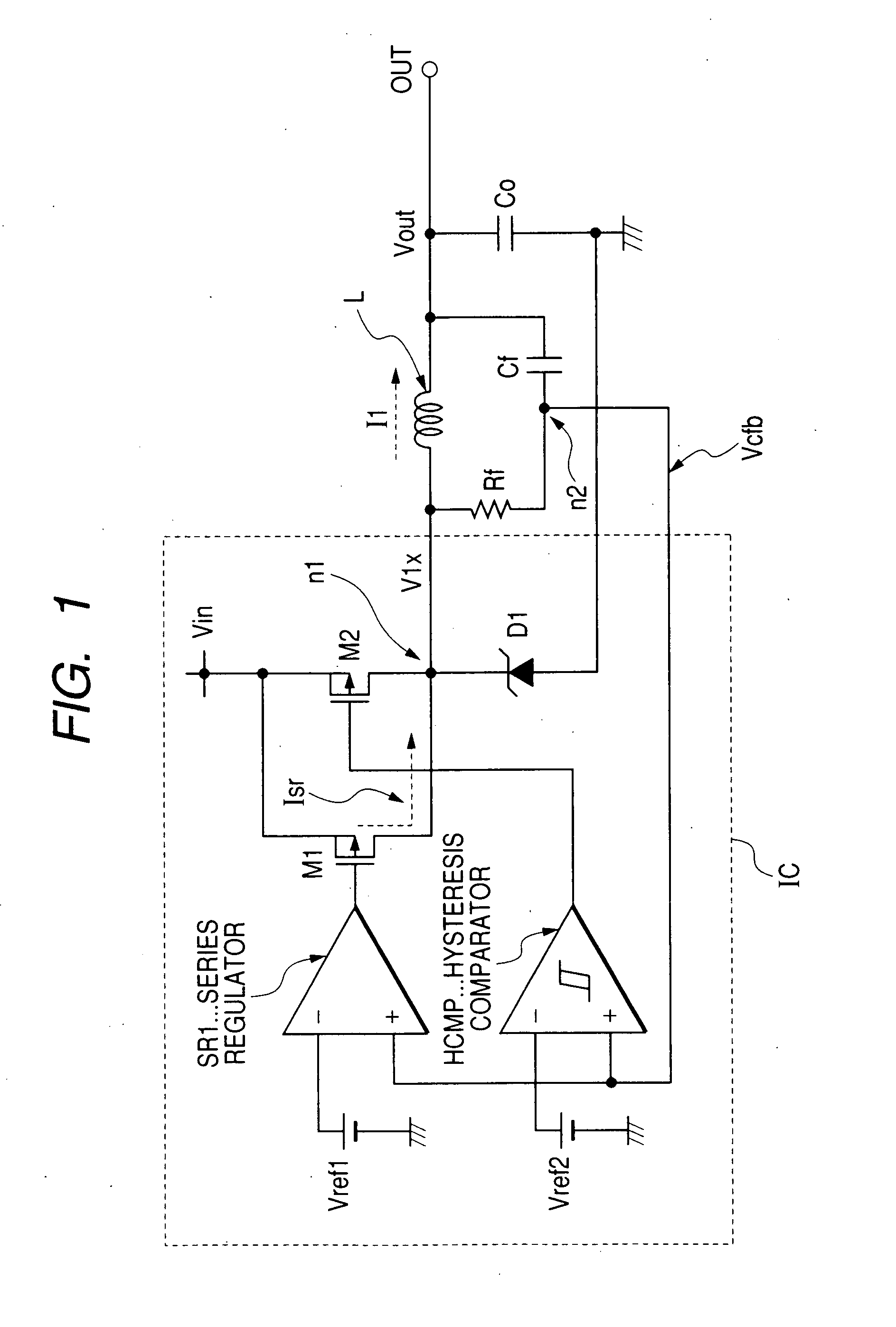
[0041]A schematic block diagram of one embodiment of a switching power supply device according to the present invention is shown in FIG. 1. The switching power supply device showing the present embodiment comprises a combination of a switching power supply circuit and a series power supply circuit. Although not restricted in particular, the switching power supply circuit includes a P channel MOSFETM2 used as a switch element and a diode D1 used as an element for voltage-clamping a back electromotive voltage developed across a coil L both of which are connected in series between a dc voltage Vin supplied from an unillustrated DC power supply such as a battery and a ground point (GND), the coil L used as an inductor connected between an intermediate node n1 between the MOSFETM2 and the diode D1 and an output terminal OUT, a smoothing capacitor C0 connected between the output terminal OUT and the ground point, a resistor Rf and a capacitor Cf provided in a series configuration, which a...


PUM


Abstract

A switching power supply circuit in which a series circuit comprising a resistive element and a capacitive element is provided in a parallel configuration with an inductor which supplies a load current to a load circuit, a voltage comparator having first and second threshold voltages discriminates a voltage obtained from a mutual connecting point of the series circuit therefrom and controls a switch element for supplying a current to the inductor, thereby varying the current supplied to the inductor in accordance with a variation in the load current is combined with a series power supply circuit which shares the load current of the load circuit.

Description

CROSS-REFERENCE TO RELATED APPLICATION[0001]The present application claims priority from Japanese Patent application JP 2000-318189 filed on Sep. 10, 2003, the content of which is hereby incorporated by reference into this application.BACKGROUND OF THE INVENTION[0002]The present invention relates to a switching power supply device and a semiconductor integrated circuit employed therein, and to a technique effective if applied to, for example, a switching power supply device mounted to a battery-driven small portable electronic terminal, and a semiconductor integrated circuit used therein.[0003]Electronic apparatuses each equipped with a microprocessor as a system control device have been on the increase in recent years. An operating frequency of the microprocessor (hereinafter called “CPU”) tends to increase more and more. The maximum operating current is also on the increase with the increase in the operating frequency. On the other hand, a portable electronic equipment or the like...

Claims


Application Information

Patent Timeline
Patent Type & Authority Patents(United States)
IPC IPC(8): G05F1/00H02J1/00G05F1/56H02M3/155H02M3/158
CPCH02M3/1584H02M2001/0009Y02B70/1466H02M3/1588H02M2001/0045H02M1/0009H02M1/0045Y02B70/10
Inventor TAZAWA, TOMOHIROYOSHIDA, SHINICHI
Owner RENESAS ELECTRONICS CORP
Why Eureka
Try Eureka