Vapor grown carbon fiber reinforced composite materials and methods of making and using same

a carbon fiber reinforced composite material and vapor growth technology, applied in the field of new continuous fiber composite materials, can solve the problems of inability to discuss or use the production method of vgcf on continuous carbon, inability to manufacture nanofiber reinforced preforms, and inability to meet the requirements of nanofiber reinforced preforms, etc., to achieve the effect of improving stiffness, strength, fracture toughness and yield

Active Publication Date: 2008-03-04
PERFORMANCE POLYMER SOLUTIONS
View PDF14 Cites 98 Cited by
  • Summary
  • Abstract
  • Description
  • Claims
  • Application Information

AI Technical Summary

Benefits of technology

[0012]There are limited literature reports of attempts to produce catalytically vapor grown carbon nanofibers on graphite or carbon substrates. However, the methods differ substantially from the method described in this invention and none report in situ production of VGCF on carbon fiber yarns, non-woven, woven or braided preforms.
[0013]Hernadi et al. (1996) report on VGCF produced on graphite flakes using an iron catalyst and acetylene/nitrogen gas mixture. They treated the graphite flakes with iron acetate and then reduced under hydrogen at 1200° C. to produce metallic iron particles. VGCF were subsequently produced at 700° C. in a flowing acetylene/nitrogen gas at atmospheric pressure. The reported yield was extremely low at 3.4% with poor quality nanofibers. Yacaman et al. (1993) also reported VCGF produced on graphite flakes using an iron catalyst and acetylene/nitrogen gas mixture. They treated the graphite flakes with an iron oxalate solution and reduced the catalyst to metallic iron particles under hydrogen at 350° C. VGCF were subsequently produced at 700° C. in a flowing acetylene/nitrogen gas at atmospheric pressure for several hours. They reported nanofibers were produced with diameters in the range of 5.0 to 20 nanometers and length around 50 micrometers, however, after 1 hour of growth graphitic structure was noted around few catalytic particles. Ivanov et al. (1995) reported production of VGCF on graphite flakes using an iron catalyst and acetylene/nitrogen gas mixture. They treated the graphite flakes with an iron oxalate solution followed by calcination at 500° C. followed by reduction with hydrogen at 500° C. for 8 hours. Under optimal conditions they reported VGCF with average diameter of 40-100 nanometers and average length of 50 micrometers and 50% amorphous carbon. Wang et al. (2002) reported VGCF produced on graphite foil by sputter coating with stainless steel (Fe:Cr:Ni—70:19:11) followed by hydrogen reduction at 660C. VGCF were subsequently produced at 0.3 torr pressure using an acetylene/nitrogen mixture. Significantly, they reported that for a pure iron or nickel catalyst on graphite no VGCF were formed. Thostenson et al. (2002) used identical process conditions as Wang et al. (2002) for growth of VGCF on a carbon fiber. They reported a nanofiber growth layer region between 200-500 nm in thickness.
[0014]U.S. Pat. Nos. 5,165,909 and 6,235,674 (and related by the same inventor

Problems solved by technology

In all these cases no discussion or method exists for the production of VGCF on continuous carbon fiber yarns and preforms with sufficient yield in

Method used


Image

  • Vapor grown carbon fiber reinforced composite materials and methods of making and using same
  • Vapor grown carbon fiber reinforced composite materials and methods of making and using same
  • Vapor grown carbon fiber reinforced composite materials and methods of making and using same

Examples


example 1

Carbon Fiber Textile Infusion with VGCF

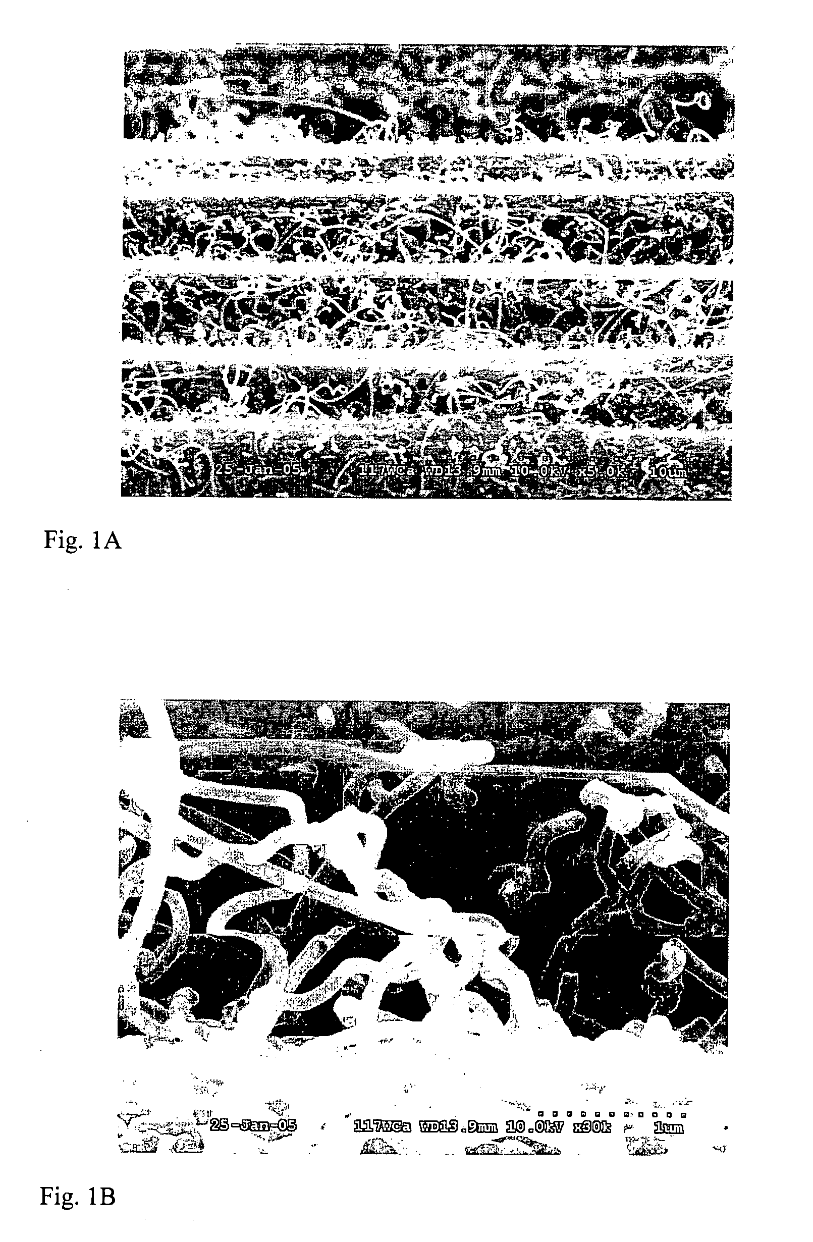
[0045]A piece of plain weave polyacrylonitrile (PAN) carbon fiber cloth was desized by solvent wash with toluene and acetone followed by oven drying. The sample was then immersed in a 125 mM solution of ferric nitrate in ethanol, and dried at 80° C. and placed in a 50 mm tube furnace. The tube furnace was immediately heated to 800° C. and nitrogen flow of 90 sccm was started when the tube furnace temperature reached 100° C. After 15 minutes at 800° C. 5 sccm of acetylene was started and the nitrogen flow was reduced to 75 sccm. After 60 minutes the acetylene was turned off and the oven was cooled to 200° C. under nitrogen flow of 75 sccm. SEM images of the resulting VGCF infused preform are shown in FIGS. 1A and 1B. In FIG. 1A, the continuous carbon fibers of the preform are clearly visible with the mass of entangled VGCF infused into the preform. In FIG. 1B at higher magnification, the morphology of the well-formed VGCF are shown fused to the ...

example 2

Carbon Fiber Textile Infusion with VGCF

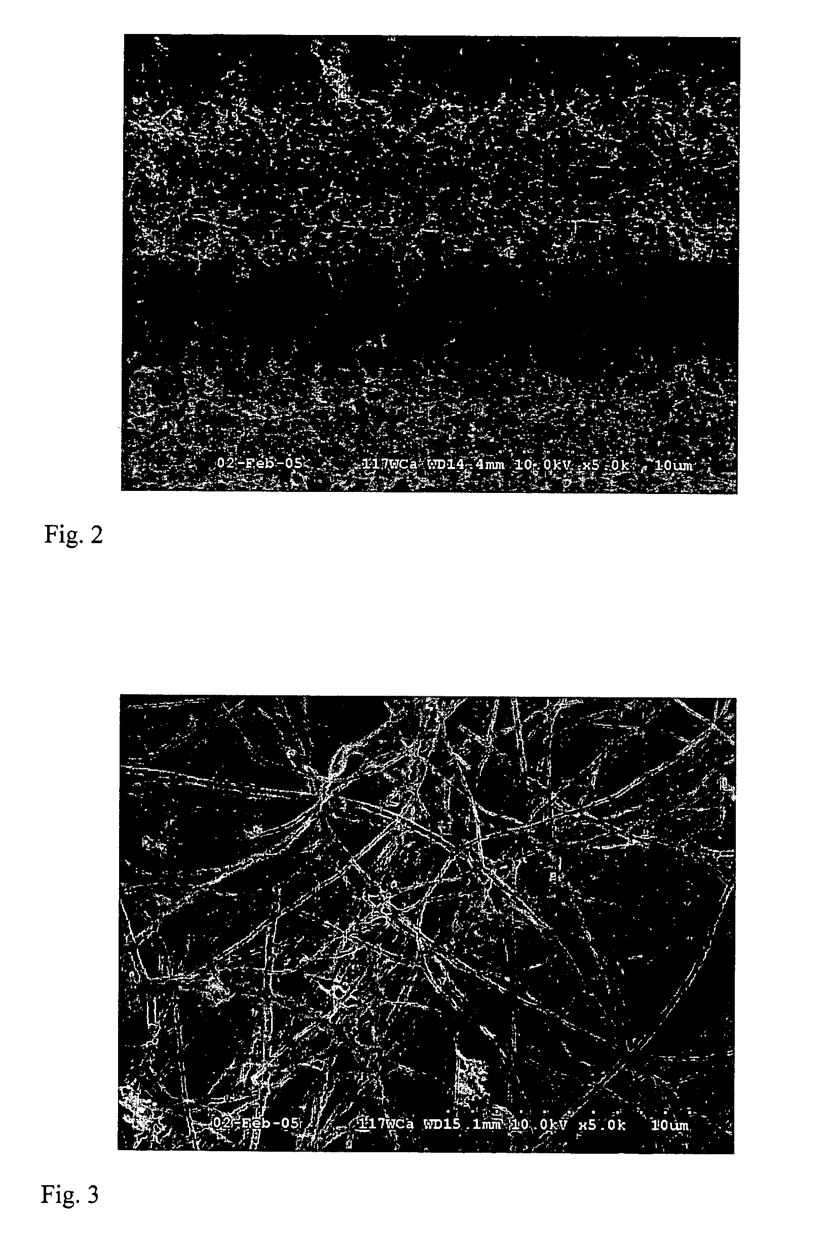
[0046]A piece of plain weave PAN carbon fiber cloth was desized by solvent wash with toluene and acetone followed by oven drying. The sample was then immersed in a 100 mM solution of ferric nitrate in ethanol, and dried at 80° C. The sample was then heated at 300° C. for 30 hours in an air convection oven, cooled, and placed in a 50 mm tube furnace. The tube furnace was heated to 750° C. and when it reached 600° C. nitrogen flow of 90 sccm was started. After 15 minutes at 750° C. 5 sccm of acetylene was started and the nitrogen flow was increased to 250 sccm. After 60 minutes the acetylene was turned off and the oven was cooled to 200° C. under nitrogen flow of 90 sccm. An SEM image of the resulting VGCF infused preform is shown in FIG. 2. In FIG. 2, the continuous carbon fibers of the preform are clearly visible with the mass of entangled VGCF infused into the preform.

example 3

Carbon Fiber Textile Infusion with VGCF

[0047]A piece of plain weave PAN carbon fiber cloth was desized by solvent wash with toluene and acetone followed by oven drying. The sample was then immersed in a freshly prepared 100 mM solution of ferric nitrate in ethanol, and dried at 80° C. The sample was then heated at 300° C. for 30 hours in an air convection oven, cooled, and placed in a 50 mm tube furnace. The tube furnace was heated to 750° C. and when it reached 600° C. nitrogen flow of 90 sccm was started. After 15 minutes at 750° C. 5 sccm of acetylene was started and the nitrogen flow was increased to 250 sccm. After 60 minutes the acetylene was turned off and the oven was cooled to 200° C. under nitrogen flow of 90 sccm. An SEM image of the resulting VGCF infused preform is shown in FIG. 3. In FIG. 3, the continuous carbon fibers of the preform are obscured by the high yield dense growth mass of entangled VGCF infused into the preform.


PUM

PropertyMeasurementUnit
Temperatureaaaaaaaaaa

Abstract

A process for producing-vapor grown carbon fiber (VGCF) reinforced continuous fiber performs for the manufacture of articles with useful mechanical, electrical, and thermal characteristics is disclosed. Continuous fiber preforms are treated with a catalyst or catalyst precursor and processed to yield VGCF produced in situ resulting in a highly entangled mass of VGCF infused with the continuous fiber preform. The resulting continuous fiber preforms are high in volume fraction of VGCF and exhibit high surface area useful for many applications. Furthermore, this invention provides for a continuous fiber preform infused with VGCF so that the carbon nanofibers are always contained within the fiber preform. This eliminates the processing steps for isolated carbon nanofibers reported in other carbon nanofiber composite approaches and therefore greatly reduces risk of environmental release and exposure to carbon nanofibers.

Description

CROSS-REFERENCE TO RELATED APPLICATION[0001]This application claims the benefit of U.S. Provisional application 60 / 544,178, filed Feb. 12, 2004, which is incorporated by reference herein to the extent it is not inconsistent with the present application.STATEMENT AS TO RIGHTS TO INVENTIONS MADE UNDER FEDERALLY SPONSORED RESEARCH AND DEVELOPMENT[0002]This work was supported in part by a grant from the United States Air Force Office of Scientific Research, STTR Contract # FA9550-04-0129. The Government of the United States of America may have certain rights in this invention.BACKGROUND OF THE INVENTION[0003]This invention relates to novel continuous fiber composites reinforced with vapor grown carbon fibers (VGCF). In particular, the invention relates to novel non-woven, woven and braided continuous fiber composite preforms that are subsequently reinforced with vapor grown carbon fibers that are grown in situ in the preform and methods of making and using same. The resulting vapor grow...

Claims


Application Information

Patent Timeline
IPC IPC(8): B05D1/12
CPCB82Y30/00C04B35/83D01F9/127D01F9/1272D01F9/1275C04B2235/3272C04B2235/405Y10T428/30Y10S977/843C04B2235/614
Inventor CURLISS, DAVID B.LINCOLN, JASON E.
Owner PERFORMANCE POLYMER SOLUTIONS
Why Eureka
Try Eureka