Optical wavelength measuring device using guiding body and diffractive structure

a wavelength measurement and optical technology, applied in the field of optical characterisation devices, can solve the problems of difficult prediction of the spectral performance characteristics of the laser in response to changes in the drive voltage of the filter, non-linear wavelength tuning of the laser, and inability to predict in advance, etc., to achieve narrow linewidth, enhance or sharpen the spatial resolution, and simplify fabrication

Inactive Publication Date: 2008-04-08
OPTITUNE
View PDF8 Cites 20 Cited by
  • Summary
  • Abstract
  • Description
  • Claims
  • Application Information

AI Technical Summary

Benefits of technology

[0022]The position sensitive detector might be a single component whose output indicates the position of incident radiation on the component. Alternatively, the position sensitive detector could comprise a photodetector array. The diffractive structure delivers radiation which is more or less collimated and this can be collected by a lens and focussed. Although the diffractive structure could diffract the radiation out of the guiding body to an external lens, it preferably diffracts it while still travelling in the guiding body to an integrated lens. This again can simplify fabrication and support further integration with other devices and / or components.
[0023]Embodiments of the present invention are particularly suitable for use in coarse WDM applications, ie where spectral separation is relatively wide as opposed to dense, with an optical input that has a narrow linewidth since this enhances, or sharpens, the spatial resolution of the position sensitive detector and thus the wavelength detection and monitoring. Embodiments are thus suitable for example for use in calibrating or characterising laser sources, or filters, for wavelength division multiplexing in communications.
[0024]Wavelength detection and monitoring techniques and apparatus can also be used with a feedback mechanism so as to control the wavelength of an optical radiation source. Embodiments of the invention may thus also provide wavelength control apparatus comprising an optical characterisation device according to the first aspect of the present invention, wherein the apparatus further comprises a detector for detecting wavelength change and feedback control means for controlling the wavelength of optical radiation input to the device in response to a detected wavelength change. Wavelength control apparatus of this type can for instance be used to provide novel wavelength referencing, or wavelength locking, apparatus for adjusting a tunable Fabry-Perot filter and / or tunable laser diode, so that the device may be tuned to a precise wavelength.

Problems solved by technology

For example, it is not generally possible to predict in advance, reliably and repeatably, the exact voltage which must be applied to a tunable silicon micromachined Fabry-Perot filter in order to tune it to a specific frequency.
As another example, a spectral filter used in a tunable laser system may have a non-linear tuning characteristic which in turn results in non-linear wavelength tuning of the laser, as disclosed in U.S. Pat. No. 6,192,059, making precise prediction of the spectral performance characteristics of the laser in response to changes in drive voltage to the filter very difficult.
Certain applications, such as WDM in telecommunications as mentioned above, as well as medical instrumentation and optical computing, can suffer from this lack of precision in performance.

Method used


Image

  • Optical wavelength measuring device using guiding body and diffractive structure
  • Optical wavelength measuring device using guiding body and diffractive structure
  • Optical wavelength measuring device using guiding body and diffractive structure

Examples


Embodiment Construction

Broad Principle of Operation

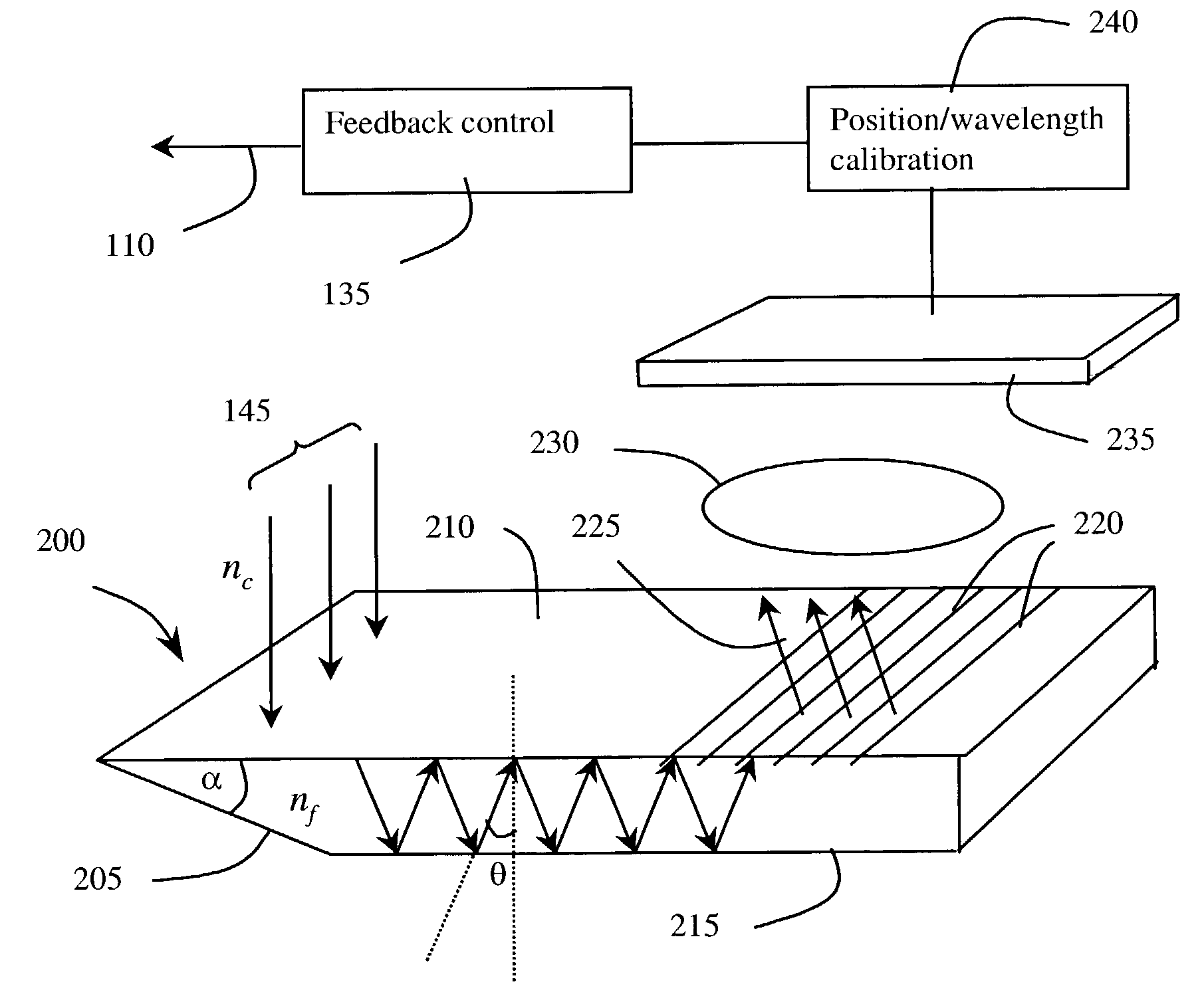
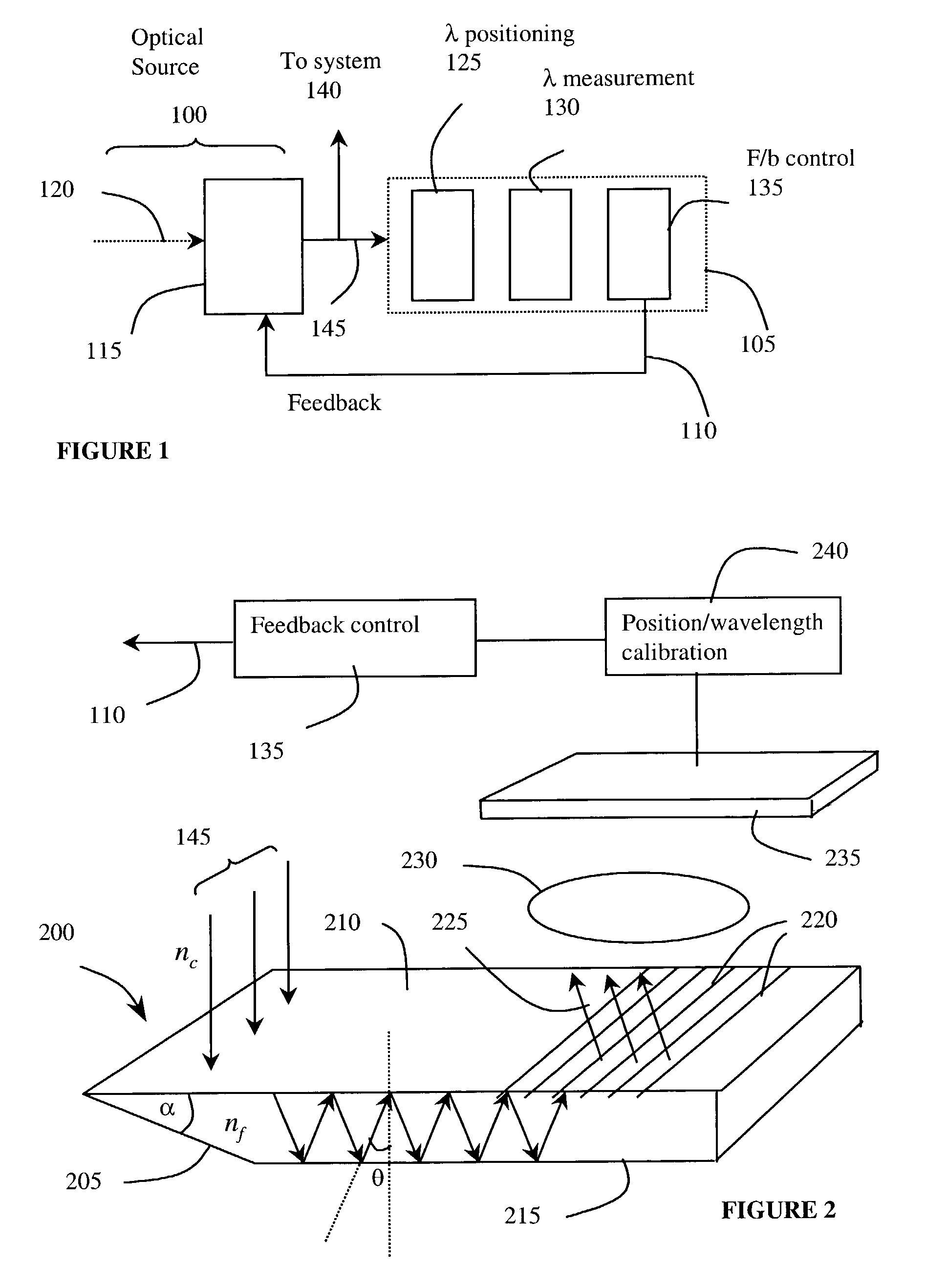
[0051]Referring to FIG. 1, an embodiment of the present invention provides an integrated arrangement and a method for monitoring the wavelength of incoming optical radiation and producing a signal when the wavelength changes. The signal can be used in a feedback loop to adjust the wavelength to keep it constant.

[0052]Such an arrangement might be used where radiation from an optical source 100 is being used to supply an optical system (not shown) which is wavelength sensitive. It is necessary to control the wavelength of radiation input 140 from the source 100 to the system. To do that, an optical characterisation arrangement based on an embodiment of the present invention picks up radiation from the source 100 and inputs it to a wavelength monitoring and feedback assembly 105. The feedback is used to tune the source 100 appropriately.

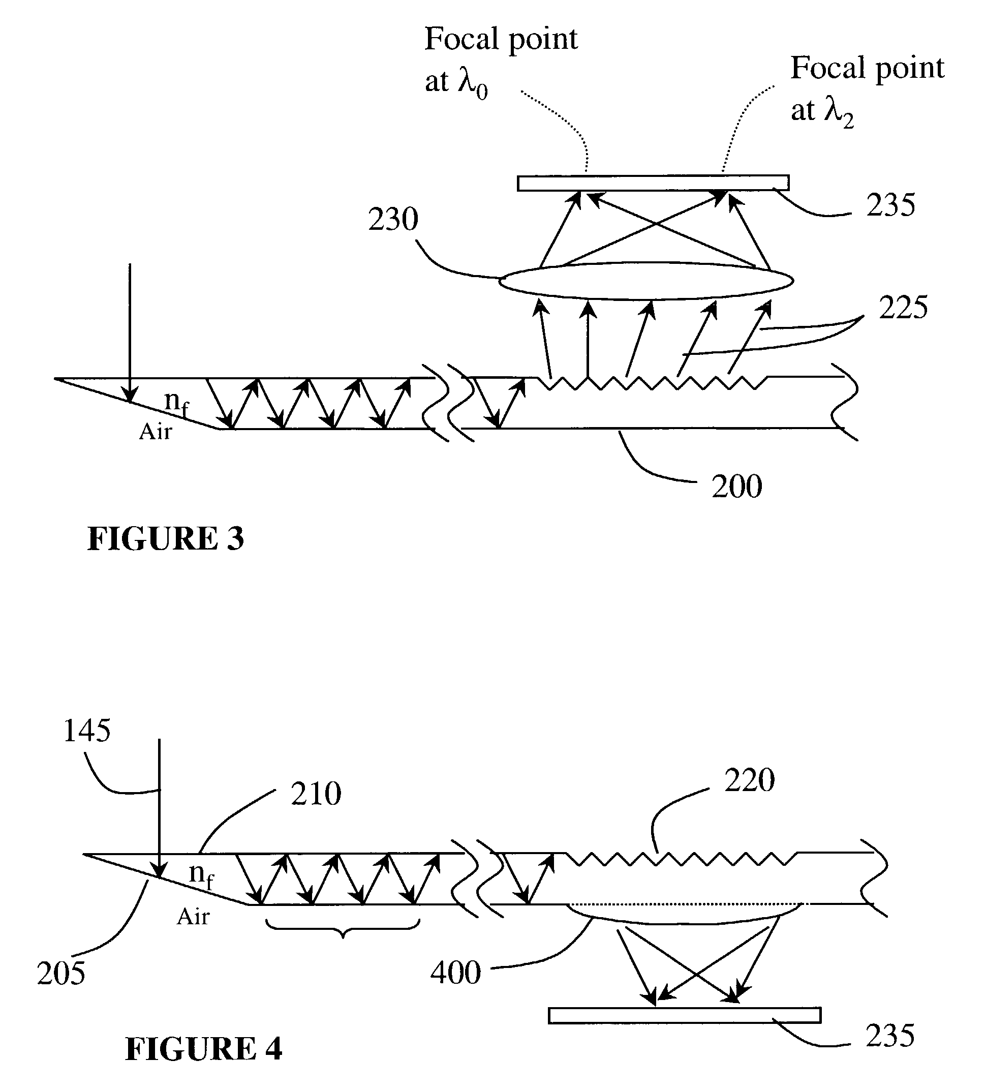
[0053]The wavelength monitoring and feedback assembly 105 is important. It performs the functions of:[0054]spatial redirect...


PUM


Abstract

An optical characterization device has a guiding body and a diffractive structure integrated with it. The guiding body delivers radiation to the diffractive structure at a preselected angle and the diffractive structure diffracts at least a portion of radiation guided to it to give spatial resolution according to wavelength. A position sensitive detector detects the position of the spatially resolved radiation and thus the radiation can be characterized according to wavelength. Embodiments can be used to monitor and adjust the wavelength of a radiation source, using a feedback connection. By using the integrated approach, a very small structure can be realized and the structure can be relatively simply fabricated and assembled. The guiding body might be either capable of supporting multimode propagation of the radiation or might be a single mode waveguide. Where it is capable of supporting multimode propagation, an input to the guiding body acts to select a mode for propagation of the radiation.

Description

[0001]BACKGROUND[0002]1. Technical Field[0003]The present invention relates to an optical characterisation device, and a method of optical characterisation. It finds particular application in calibrated wavelength monitoring, for instance of optical sources or filters.[0004]2. Related Art[0005]It can be important that the wavelength characteristics of optical sources and filters are known with precision. This is important for example in wavelength division multiplexing (WDM) in optical networks where the wavelengths carried in the networks must be distinguishable from one another and must be individually detectable at a receiver.[0006]It is known to use lasers and / or filters in this kind of environment which have known wavelength characteristics, and it is known to use tunable components so that for instance a WDM scheme can be varied or a replacement device can be adjusted to meet the requirements of a damaged one.[0007]However, the precise spectral performance characteristics of a...

Claims


Application Information

Patent Timeline
Patent Type & Authority Patents(United States)
IPC IPC(8): G02B6/34G01J3/18G01J3/28G02B6/12G02B6/28
CPCG01J3/02G01J3/0205G01J3/0256G01J3/18G01J3/28G02B6/12007G02B6/2848
Inventor SIDORIN, YAKOV
Owner OPTITUNE
Why Eureka
Try Eureka