Methods for depositing tungsten layers employing atomic layer deposition techniques

a technology of atomic layer deposition and tungsten, which is applied in the direction of chemical vapor deposition coating, solid-state devices, coatings, etc., can solve the problems of compromising the structural and operational integrity of the underlying portions of the integrated circuit being formed, the need for more complexity in the chamber design and gas flow technique, and the conventional cvd method of tungsten depositing

Inactive Publication Date: 2008-07-29
APPLIED MATERIALS INC
View PDF514 Cites 100 Cited by
  • Summary
  • Abstract
  • Description
  • Claims
  • Application Information

AI Technical Summary

Problems solved by technology

These requirements become more critical as substrate size increases, creating a need for more complexity in chamber design and gas flow technique to maintain adequate uniformity.
Formation of film layers at a high deposition rate while providing adequate step coverage are conflicting characteristics often necessitating the sacrifice of one to obtain the other.
Depositing tungsten by conventional CVD methods, however, is attendant with several disadvantages.
Also, blanket deposition of a tungsten layer on a semiconductor wafer is time-consuming at temperatures below 400° C. The deposition rate of tungsten may be improved by increasing the deposition temperature to, for example, about 500° C. to about 550° C. However, temperatures in this higher range may compromise the structural and operational integrity of the underlying portions of the integrated circuit being formed.
Use of tungsten has also frustrated photolithography steps during the manufacturing process as it results in a relatively rough surface having a reflectivity of 70% or less than that of silicon (thickness and wavelength dependent).
Further, tungsten has proven difficult to deposit uniformly.
Poor surface uniformity typically increases film resistivity.

Method used


Image

  • Methods for depositing tungsten layers employing atomic layer deposition techniques
  • Methods for depositing tungsten layers employing atomic layer deposition techniques
  • Methods for depositing tungsten layers employing atomic layer deposition techniques

Examples


example 1

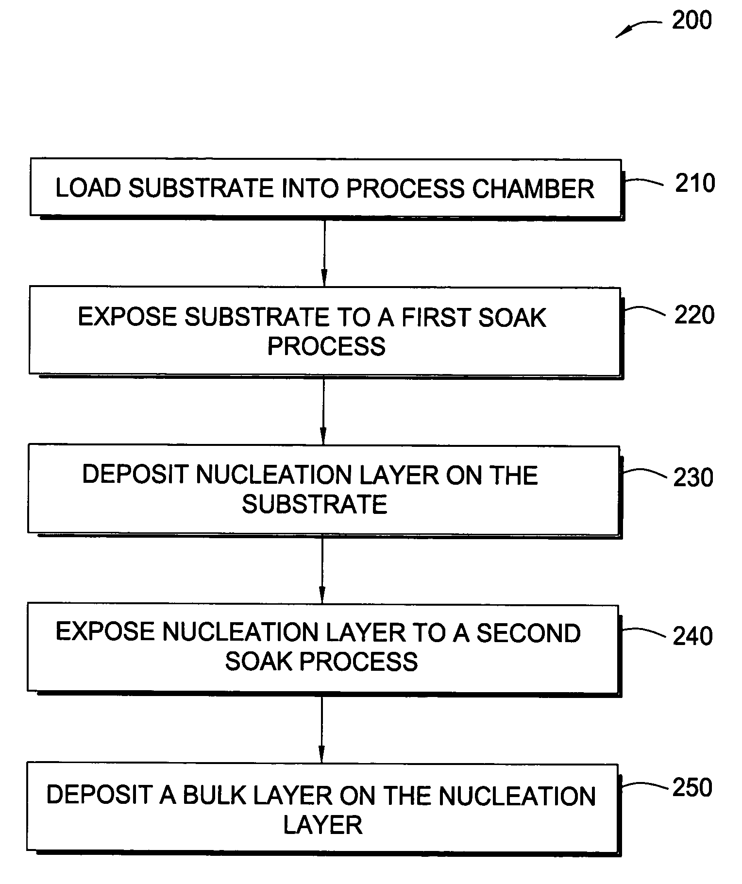
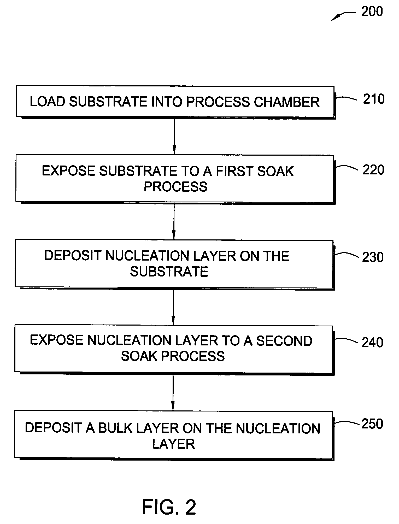
[0075]The substrate was placed into an ALD chamber and exposed to a soak process under the following conditions:[0076]Reagent: B2H6;[0077]Pressure: about 15 Torr;[0078]Temperature: about 300° C.;[0079]Flow rates: 300 sccm 5% B2H6 in Ar; and[0080]Duration: about 30 seconds.

[0081]Next, a tungsten nucleation layer was formed on the barrier layer in the same ALD chamber from the previous soak process using an ALD process under the following conditions:[0082]Reagents: WF6 and B2H6;[0083]Pressure: about 5 Torr;[0084]Temperature: about 300° C.;[0085]Flow rates: pulse A: 20 sccm WF6 and 300 sccm Ar;[0086]pulse B: 150 sccm B2H6 and 150 sccm H2;[0087]Ar-purge: 500 sccm;[0088]Cycle duration: Ar-purge: 0.5 seconds;[0089]pulse A: 0.2 seconds;[0090]Ar-purge: 0.5 seconds; and[0091]pulse B: 0.2 seconds.

[0092]The cycle was repeated 4 times to form a nucleation layer with a thickness of about 12 Å. Thereafter, the substrate was maintained in the ALD chamber and exposed to a second soak process under ...

example 2

[0099]The substrate was placed into an ALD chamber and exposed to a soak process under the following conditions:[0100]Reagent: B2H6;[0101]Pressure: about 15 Torr;[0102]Temperature: about 300° C.;[0103]Flow rates: 300 sccm 5% B2H6 in Ar; and[0104]Duration: about 30 seconds.

[0105]Next, a tungsten nucleation layer was formed on the barrier layer in the same ALD chamber as used in the prior soak process using an ALD process under the following conditions:[0106]Reagents: WF6 and SiH4;[0107]Pressure: about 10 Torr;[0108]Temperature: about 300° C.;[0109]Flow rates: pulse A: 30 sccm WF6 and 300 sccm Ar;[0110]pulse B: 20 sccm SiH4 and 300 sccm H2;[0111]Ar purge: 500 sccm;[0112]Cycle duration: Ar-purge: 0.5 seconds;[0113]pulse A: 0.3 seconds;[0114]Ar-purge: 0.5 seconds; and[0115]pulse B: 0.3 seconds.

[0116]The cycle was repeated 4 times to form a nucleation layer with a thickness of about 30 Å. Thereafter, the substrate was transferred to a CVD chamber and exposed to a second soak process unde...

example 3

[0123]The substrate was placed into a CVD chamber and exposed to a soak process under the following conditions:[0124]Reagent: B2H6;[0125]Pressure: about 90 Torr;[0126]Temperature: about 400° C.;[0127]Flow rates: 200 sccm 5% B2H6 in Ar; and[0128]Duration: about 24 seconds.

[0129]Next, a tungsten nucleation layer was formed on the barrier layer in the CVD chamber from the previous soak process using a pulsed-CVD process under the following conditions:[0130]Reagents: WF6 and SiH4;[0131]Pressure: about 30 Torr;[0132]Temperature: about 400° C.;[0133]Flow rates: 60 sccm WF6 and 30 sccm SiH4;[0134]Pulse duration: 1.5 seconds;

[0135]The pulsed-CVD process was continued until the nucleation layer had a thickness of about 50 Å. Thereafter, the substrate was kept in the CVD chamber and a second nucleation layer was deposited on the first nucleation layer. The second nucleation layer was deposited by a traditional CVD process to a thickness of about 200 Å under the following conditions:[0136]Reag...


PUM

PropertyMeasurementUnit
temperaturesaaaaaaaaaa
reflectivityaaaaaaaaaa

Abstract

In one embodiment of the invention, a method for forming a tungsten-containing layer on a substrate is provided which includes positioning a substrate containing a barrier layer disposed thereon in a process chamber, exposing the substrate to a first soak process for a first time period and depositing a nucleation layer on the barrier layer by flowing a tungsten-containing precursor and a reductant into the process chamber. The method further includes exposing the nucleation layer to a second soak process for a second time period and depositing a bulk layer on the nucleation layer. In one example, the barrier layer contains titanium nitride, the first and second soak processes independently comprise at least one reducing gas selected from the group consisting of hydrogen, silane, disilane, dichlorosilane, borane, diborane, derivatives thereof and combinations thereof and the nucleation layer may be deposited by an atomic layer deposition process or a pulsed chemical vapor deposition process while the bulk layer may be deposited by a chemical vapor deposition process or a physical vapor deposition process.

Description

CROSS-REFERENCE TJO RELATED APPLICATIONS [0001]This application is a continuation-in-part of U.S. patent application Ser. No. 10 / 418,728, entitled “Method for Depositing Refractory Metal Layers Employing Sequential Deposition Techniques,” filed on Apr. 18, 2003, which is a continuation-in-part of U.S. patent Ser. No. 10 / 268,195 filed Oct. 10, 2002 now U.S. Pat. No. 6,797,340, filed Oct. 10, 2002, which claims priority to U.S. Provisional Patent Application Ser. No. 60 / 328,451, entitled “Method and Apparatus for Depositing Refractory Metal Layers Employing Sequential Deposition Techniques,” filed on Oct. 10, 2001, which are all hereby incorporated by reference in their entirety. This application is also a continuation-in-part of U.S. patent No. application Ser. No. 10 / 879,448, entitled, “Method for Depositing Refractory Metal Layers Employing Sequential Deposition Techniques,” filed Jun. 29, 2004, which is a continuation of U.S. patent Ser. No. 10 / 268,195 filed Oct. 10, 2002 now U.S....

Claims


Application Information

Patent Timeline
Patent Type & Authority Patents(United States)
IPC IPC(8): H01L21/44
CPCC23C16/0281C23C16/08C23C16/14C23C16/45525H01L21/28556H01L21/28562H01L21/76855H01L21/76856H01L21/7687H01L21/76876H01L21/76877H01L21/76843H01L2221/1089
Inventor LAI, KEN KAUNGRAJAGOPALAN, RAVIKHANDELWAL, AMITMOORTHY, MADHUGANDIKOTA, SRINIVASCASTRO, JOSEPHGELATOS, AVERGINOS V.KNEPFLER, CHERYLJIAN, PINGFANG, HONGBINHUANG, CHAO-MINGXI, MINGYANG, MICHAEL X.CHUNG, HUABYUN, JEONG SOO
Owner APPLIED MATERIALS INC
Why Eureka
Try Eureka