

Metallisation
a technology of organometallic compounds and metals, applied in the field of metalisation, can solve the problems of high density and inability to manufacture interconnects, and achieve the effect of reducing gas flows
- Summary
- Abstract
- Description
- Claims
- Application Information
AI Technical Summary
Benefits of technology
Problems solved by technology
Method used
Image

Examples
example 1
[0131]First of all, glass substrates of Corning 7059 glass were cleaned according to the following process:[0132]a. Pre-cut substrates of 1 cm2 were added to Desolvit 3000 (a commercial cleaning material) and exposed to ultrasonic agitation for 30 minutes.[0133]b. The substrates were then rinsed in warm deionised water (approximately 40° C.) for 10 minutes.[0134]c. The substrates were then briefly rinsed in deionised water.[0135]d. Finally, blown nitrogen was used to dry the substrates.
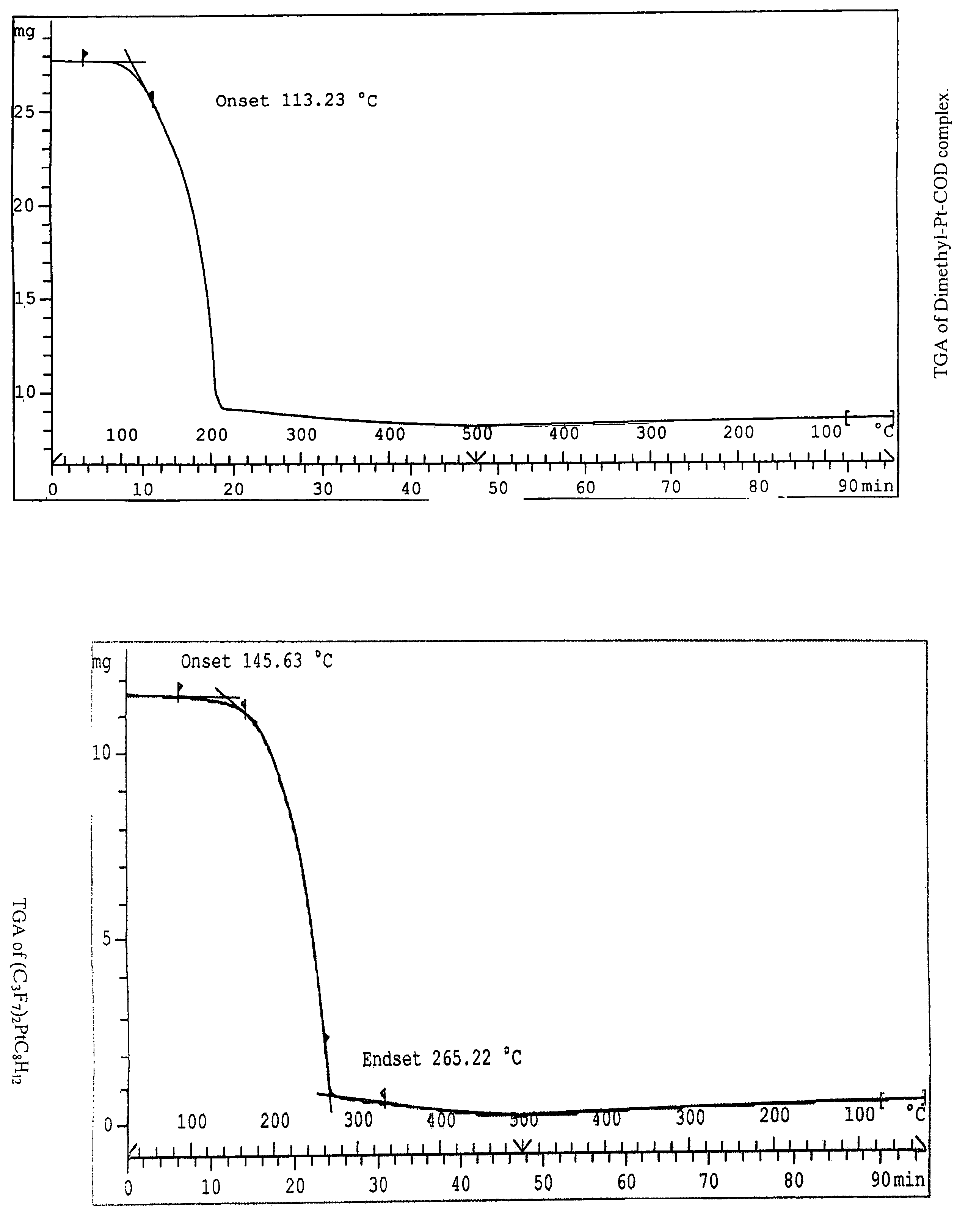
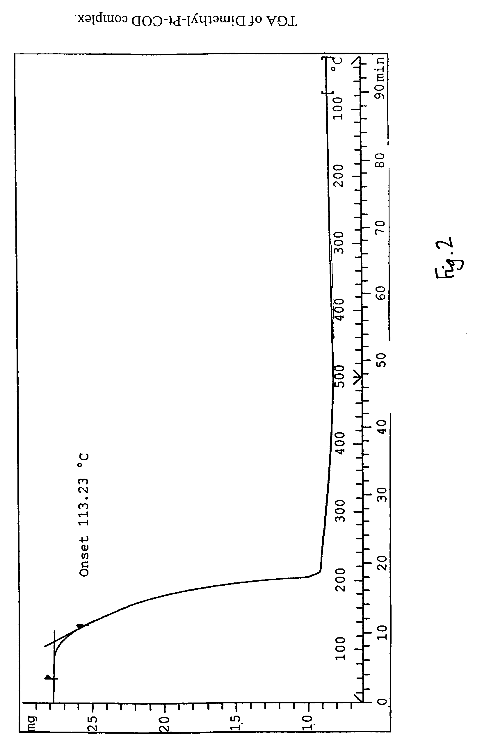
[0136]100 mg of dimethyl-platinum cyclooctadiene was weighed out using a balance (a Mettler Toledo AB54-S) and added to a molybdenum covered boat. The substrates were then coated to a glass slide which was attached by iridium wire before being attached to a ‘rotatilt table’.
[0137]The dimethyl-platinum cyclooctadiene was then deposited via evaporation onto a glass substrate. The evaporation procedure comprises placing the boat and the cleaned substrate in a vacuum coating unit. A bell jar and guard wer...
example 2
[0151]Bis-(perfluoropropyl)-1,5-cyclooctadiene platinum (II) was then used to coat a glass substrate.
[0152]Bis-(perfluoropropyl)-1,5-cyclooctadiene platinum (II) was prepared as follows. A solution of bis-methyl platinum (II) cyclooctadiene (2.6 g) was dissolved in 3 cm3 of dry methylene chloride (i.e. dichloromethane) to which 2.4 cm3 of n-perfluoropropyl iodide was slowly added under an inert atmosphere of argon. The reaction was shaken for 5 days in ambient conditions under an argon atmosphere, during which time a yellow / cream precipitate formed. The reaction mixture was filtered off and the solvent removed by evaporation resulting in a yellow product. A solution of the product in methylene chloride was then filtered through a short fluorosil column. The fractions containing the desired product were combined and a creamy white product crystallised out in a methylene chloride / pentane solution. A 20.5% yield of bis-(perfluoropropyl)-1,5-cyclooctadiene platinum (II) was obtained.
[01...
example 3
[0180]A glass substrate was cleaned as before and 100 mg of bis-(perfluoropropyl)-1,5-cyclooctadiene platinum (II) was deposited onto the substrate.
[0181]The coated glass substrate was exposed to UV radiation as before.
[0182]The following 4-stage reduction process was then used to reduce the deposited bis-(perfluoropropyl)-1,5-cyclooctadiene platinum (II) to platinum:[0183]Stage 1: heating the coated substrate from about 25° C. to about 120° C. at a ramp rate of about 2° C. per minute; maintaining the temperature at about 80° C. for about 60 minutes; and then cooling the substrate from about 80° C. to about 25° C. at a ramp rate of about 10° C. per minute; wherein N2 is flowed over the coated substrate at a rate of about 50 ml per minute. This stage results in sublimation of any non-exposed area;[0184]Stage 2: heating the substrate from about 25° C. to about 250° C. at a ramp rate of about 5° C. per minute; maintaining the temperature at about 250° C. for about 60 minutes; and then ...
PUM
| Property | Measurement | Unit |
|---|---|---|
| temperature | aaaaa | aaaaa |
| temperature | aaaaa | aaaaa |
| temperature | aaaaa | aaaaa |
Abstract
Description
Claims
Application Information