Monitoring method and/or apparatus

a monitoring method and/or a technology of a monitoring device, applied in the field of monitoring methods and/or apparatus, can solve the problems of affecting the accuracy of sensor readings, and affecting the accuracy of measurement results, etc., to achieve the effect of facilitating sensor recalibration, reducing the risk of recurrence, and minimally invasiv

Active Publication Date: 2008-08-19
RGT UNIV OF CALIFORNIA
View PDF10 Cites 42 Cited by
  • Summary
  • Abstract
  • Description
  • Claims
  • Application Information

AI Technical Summary

Benefits of technology

[0013]In more specific embodiments, the invention involves a method and / or apparatus for monitoring of substances in interstitial fluid under the skin of a human or animal or under the outer layer of a plant using out-of-plane microneedles. For humans and animals, this can allow painless everyday usage.
[0017]In further example embodiments, a group of microneedles in included in a system along with a system and / or method for automatic calibration. Automatic calibration allows the system to provide reliable monitoring results without the need for additional calibration methods, such as a needle-stick test. According to specific embodiments of the invention, the dialysis system use in combination with the out-of-plane microneedles facilitates sensor recalibration.
[0018]The present invention in specific embodiments provides a disposable sensor system that is minimally invasive and provides accurate sensor readings and painless and easy sensor application. An example of such a system system consists of hollow out-of-plane microneedles to sample glucose from the interstitial fluid of the epidermis, an integrated dialysis membrane and an integrated electrochemical enzyme-based flow-through glucose sensor.
[0019]In a further and very specific example embodiment, an array of between about 600 to 1500 microneedles is placed on an approximately 8 mm×8 mm substrate. One advantage of using an array of out-of-plane microneedles is that the resulting membrane area is large enough for effective diffusion but the insertion of a number of out-of-plane microneedles is painless since the needles are in fact very small, actually in the micro-meter range. In addition the needle array is easy to apply by fixing (e.g., by taping) or pressing the device onto the skin rather the inserting a dialysis probe at a shallow angle several millimeter long underneath the skin. According to specific embodiments of the invention, a monitoring device using microneedles can be applied to the skin and effectively sample substances in interstitial without penetrating deeply enough to impact nerve endings.

Problems solved by technology

Currently proposed systems for monitoring substances of interest, such as glucose, using small sampling and monitoring devices have a number of difficulties.
A disadvantage of using a large “micro” dialysis probe is a generally painful insertion procedure that generally requires trained personnel to implant the probe underneath the skin.
Thus, present microdialysis proposals do not easily allow for painless everyday usage.
While diabetes is the leading cause of blindness, kidney failure and non-traumatic amputation of the lower limp, other severe complications associated with hyperglycemia (high glucose levels) and hypoglycemia (low glucose levels) are nerve damage, heart disease, coma and brain damage.
The traditional fingerstick test typically takes periodic samples, but this monitoring can miss periods of hyperglycemia and hypoglycemia, especially during sleep.
However, it is believed that these systems cannot provide an accurate everyday glucose level control and still require periodic fingerstick tests for sensor recalibration.
While frequent and long periods of hyperglycemic blood glucose levels can account for many long-term complications, hypoglycemia can cause sudden coma and brain damage.
Periodic fingerstick tests often fail to detect all hypoglycemic and hyperglycemic events since glucose levels can change rapidly.
In particular, nocturnal hypoglycemia often remains undetected.

Method used


Image

  • Monitoring method and/or apparatus
  • Monitoring method and/or apparatus
  • Monitoring method and/or apparatus

Examples


example 1

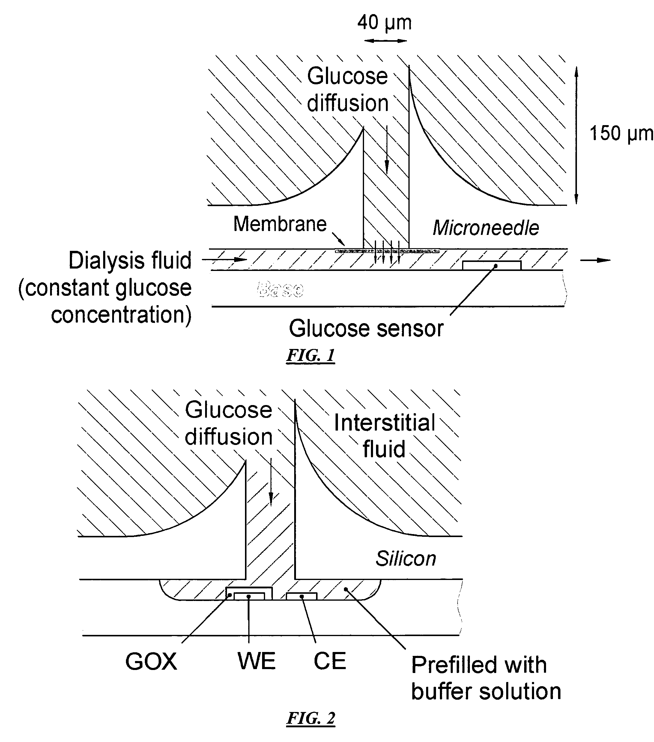
[0058]FIG. 1 is a schematic diagram of an example microneedle-based continuous monitor wherein microneedle lumens are filled with interstitial fluid by capillary action and a substance of interest diffuses through the integrated dialysis membrane into dialysis fluid that is pumped past an integrated enzyme-based flow-through sensor according to specific embodiments of the invention. In this example, an array of hollow out-of-plane microneedles is used to penetrate the skin and to interface with the interstitial fluid. A dialysis membrane separates the interstitial fluid and the dialysis fluid; thus, no interstitial fluid is extracted during operation. Dialysis fluid with a known constant glucose concentration is continuously pumped past the dialysis membrane and an integrated sensor (e.g., for glucose). Glucose diffuses through the microneedles and through the dialysis membrane into or out of the dialysis fluid. The concentration change in dialysis fluid is measured—it depends on th...

example 2

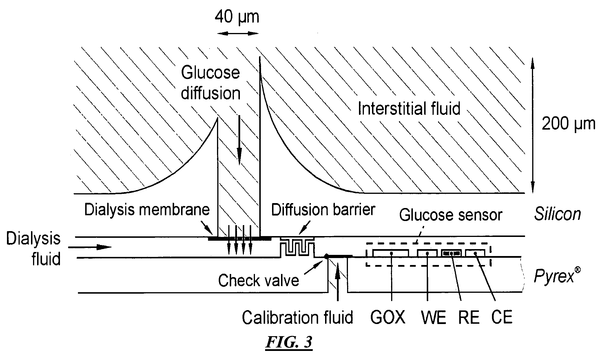
[0059]FIG. 3 is a schematic diagram of an example microneedle-based continuous monitor including a separate calibration fluid system according to specific embodiments of the invention. In this further specific example, operation of the example sensor can be understood as follows. An group of, for example, about 200 μm long hollow out-of-plane microneedles are used to penetrate the topmost layer of the skin, allowing their opening to come in contact with interstitial fluid from the epidermis. Once the microneedles are either filled with interstitial fluid or once sufficient time has elapsed for a substance of interest to diffuse into prefilled needles, the substance of interest (e.g., glucose) diffuses through the dialysis membrane into dialysis fluid, keeping unwanted substances (e.g., larger protein molecules) outside of the dialysis area, thus improving the sensor long-term stability.

[0060]Various detection strategies can be used for detecting substances of interest. Different str...

example 3

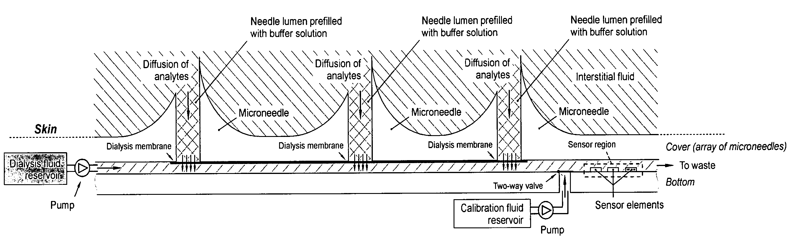
[0067]FIG. 4 illustrates an example schematic diagram of a sensor system showing three representative microneedles, a dialysis membrane, fluid reservoirs and pumps, according to specific embodiments of the present invention. In this example system, separate calibration and dialysis fluids reservoirs are used, with two micropumps and valves as shown.


PUM


Abstract

A method and apparatus for substance monitoring. One application is an easy to handle continuous glucose monitor using a group of hollow out-of-plane silicon microneedles to sample substances in interstitial fluid from the epidermal skin layer. The glucose of the interstitial fluid permeates a dialysis membrane and reaches a sensor. Using MEMS technology, for example, allows well-established batch fabrication at low cost.

Description

CROSS REFERENCE TO RELATED APPLICATIONS[0001]This application claims priority from provisional patent application 60 / 464,221 filed 18 Apr. 2003 and incorporated herein by reference.[0002]The Invention was made with government support under Grant (Contract) No. F30602-00-2-0566 awarded by the Department of Defense. The Government has certain rights to this invention.COPYRIGHT NOTICE[0003]Pursuant to 37 C.F.R. 1.71(e), Applicants note that a portion of this disclosure contains material that is subject to copyright protection (such as, but not limited to, source code listings, screen shots, user interfaces, or user instructions, or any other aspects of this submission for which copyright protection is or may be available in any jurisdiction.). The copyright owner has no objection to the facsimile reproduction by anyone of the patent document or patent disclosure, as it appears in the Patent and Trademark Office patent file or records, but otherwise reserves all copyright rights whatsoe...

Claims


Application Information

Patent Timeline
Patent Type & Authority Patents(United States)
IPC IPC(8): A61B5/05
CPCA61B5/14514A61B5/14525A61B5/1486A61B5/14532A61B2562/028A61B2560/0223
Inventor ZIMMERMANN, STEFANSTOEBER, BORISLIEPMANN, DORIANPISANO, ALBERT
Owner RGT UNIV OF CALIFORNIA
Why Eureka
Try Eureka