Image forming material

a technology of image forming and material, applied in the field of image forming materials, can solve the problems of insufficient adhesive property to the substrate, insufficient adhesive property, and document that does not disclose anything about the smoothness of the thermoplastic resin layer, and achieves superior contact characteristics with glass substrates. high speed

Active Publication Date: 2008-10-14
FUJIFILM CORP +1
View PDF15 Cites 4 Cited by
  • Summary
  • Abstract
  • Description
  • Claims
  • Application Information

AI Technical Summary

Benefits of technology

[0012]An object of the present invention is to provide an image forming material that achieves a smooth coat surface with an even layer thickness, without coating irregularities, color irregularities, cissing and pinholes, and is superior in contact characteristics with glass substrate. Moreover, another object is to provide an image forming material which, upon transferring a photosensitive resin layer of the image forming material from a temporary support to a permanent support, allows the temporary support to carry out the transferring process at high speeds without causing a defective transferring (generation of bubbles) due to differences in level or the like caused by scratches on the permanent support and the above-mentioned proceeding pixels.

Problems solved by technology

However, these are still insufficient in adhesive property to the substrate, and, in particular, fail to provide a sufficient adhesive property to the substrate upon carrying out a transferring process onto a glass substrate and a substrate bearing semiconductors.
Moreover, this document does not disclose anything about smoothness on the thermoplastic resin layer.
Moreover, in recent years, there have been strong demands for a high-speed transferring property from the viewpoint of cost reduction, and in the case when certain irregularities exist on a substrate to be transferred, upon carrying out the high-speed transferring process of a very thin photopolymerizable layer thereon, a problem is raised in which bubbles and the like are included between the photopolymerizable layer and the substrate to cause a defective transferring process.
For example, upon producing a multi-color image such as a color-filter forming process, this problem occurs when the second color photosensitive resin layer is formed on the first color pixel.
Further, in the case when, upon producing a printed substrate and the like, fine scratches and dents exist on a copper surface of a copper-clad laminate due to a surface smoothing process, this problem occurs when a dry film resist layer is transferred thereon.
Although this method is certainly effective, it is not sufficient in transferring a non-adhesive photosensitive resin layer onto a permanent support having irregularities that have the similar thickness as the thickness of the layer at room temperature, without causing bubbles thereon.
However, in the case when, in order to increase the transferring speed, a flexible material is used for the resin to form the alkali-soluble thermoplastic resin layer or when a great amount of plasticizer is added, a phenomenon (hereinafter, referred to as reticulation) occurs in which fine wrinkles are generated on the intermediate layer upon forming the alkali-soluble thermoplastic resin layer and the intermediate layer on the temporary support, causing irregularities to remain on the surface.
The reticulation causes a problem in which smoothness in the photosensitive resin layer applied onto the intermediate layer is interrupted.
For this reason, it has been difficult to achieve both of the high-speed transferring property and the prevention of reticulation.
Moreover, the developing process tends to fail to sufficiently dissolve the plasticizer in the developer, with the result that troubles in transporting solution, such as pipe clogging in the developing vessel, tend to occur frequently.

Method used


Image

  • Image forming material
  • Image forming material
  • Image forming material

Examples


example 1

[0126]Onto a temporary support of a polyethylene terephthalate film having a thickness of 75 μm was applied a coat solution having the following formulation Cu1, and dried thereon to form a thermoplastic resin layer having a dry film thickness of 20 μm.

[0127]

Thermoplastic resin layer formulation Cu1:Methyl methacrylate / 2-ethyl hexyl acrylate / benzyl5.8partsmethacrylate / methacrylic acid copolymer(Copolymer composition ratio (molar ratio) = 55 / 30 / 10 / 5,Weight-average molecular weight = 100,000, Tg ≈ 70° C.)Styrene / acrylic acid copolymer13.2parts(Copolymer composition ratio (molar ratio) = 65 / 35,Weight-average molecular weight = 10,000, Tg ≈ 100° C.)Compound formed by dehydration-condensation of9parts2 equivalents of pentaethylene glycolmonomethacrylate with bisphenolA (BPE-500 made by Shin-Nakamura Chemical Co., Ltd.)Methylethyl ketone53partsMethanol17partsCopolymer of the invention shown in Table 10.55part(20% by weight solution in methylisobutyl ketone)

[0128]

TABLE 1MonomerCopolymeri-M...

examples 2 to 16

[0186]The same processes as example 1 were carried out except that, instead of “the copolymer of the invention shown in Table 1” in the formulation of the thermoplastic resin layer Cu1 of example 1, “the copolymers of the invention” in examples 2 to 16 respectively shown in Table 1 were used so that image forming materials of examples 2 to 16 were formed to prepare a color filter.

example 17

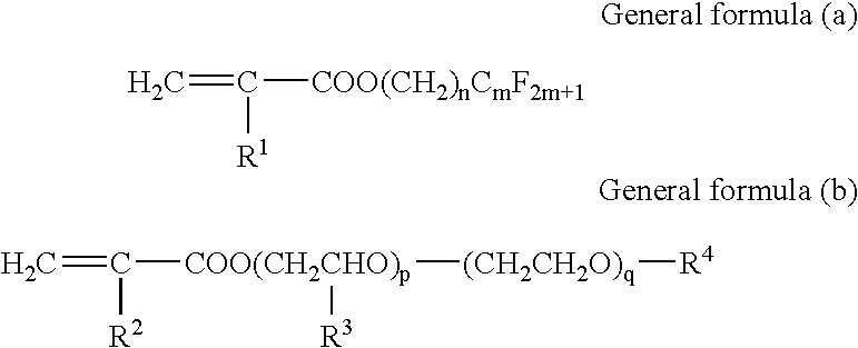
[0187]The same processes as example 1 were carried out, except that, in place of the copolymer of the invention that was commonly used in the formulations of the coating solutions for respective photosensitive layers (red, green, blue, black) in example 1, a copolymer (weight average molecular weight: 30,000) of 60% of C8F17SO2N(C4H9)CH2CH2OCOCH═CH2 and 40% of H(O(CH3)CHCH2)6OCOCH═CH2 was used, so that an image forming material was formed to prepare a color filter.


PUM

PropertyMeasurementUnit
thicknessaaaaaaaaaa
thicknessaaaaaaaaaa
thicknessaaaaaaaaaa

Abstract

The present invention relates to an image forming material in which at least an alkali-soluble thermoplastic resin layer and a photosensitive resin layer are formed on a support in this order. At least the thermoplastic resin layer of the image forming material includes a copolymer comprising monomers represented by the following general formula (a) and the following general formula (b), a content ratio by mass of the monomers represented by general formula (a) to the monomers represented by general formula (b) is in a specific range.

Description

BACKGROUND OF THE INVENTION[0001]1. Field of the Invention[0002]The present invention relates to an image forming material that is advantageously used for an image formation by the use of a transferring process, such as a production of a color filter to be used for a manufacturing process of a color liquid-crystal display and the like.[0003]2. Description of the Related Art[0004]An image forming material, which is used for forming a photosensitive resin layer on a substrate serving as a body to be transferred, by transferring the photosensitive resin layer formed on a support onto the substrate, has been well known by, for example, Japanese Patent Application Publication (JP-B) No. 56-40824. This image forming material is used for manufacturing products such as printed circuits, intaglio / letterpress printing plates, name plates, multi-color trial print samples, offset printing plates and screen printing stenciles. The above-mentioned image forming material is normally constituted by...

Claims


Application Information

Patent Timeline
Patent Type & Authority Patents(United States)
IPC IPC(8): G03F7/00G03F7/004G02B5/20G03F7/11G03F7/09G03F7/16
CPCG03F7/0007G03F7/092G03F7/161
Inventor GOTO, HIDENORI
Owner FUJIFILM CORP
Why Eureka
Try Eureka