
Method and system for automating issue resolution in manufacturing execution and material control systems

a technology of manufacturing execution and material control system, applied in the direction of program control, total factory control, instruments, etc., can solve the problems of continuous performance of equipment and systems (e.g., percentage up-time), error conditions, and how long can a tool, carrier or other piece of equipment be expected to run, so as to reduce productivity, increase productivity, and speed up the effect of turn around tim

Inactive Publication Date: 2008-10-21
INT BUSINESS MASCH CORP
View PDF8 Cites 27 Cited by
  • Summary
  • Abstract
  • Description
  • Claims
  • Application Information

AI Technical Summary

Benefits of technology

The ISR system increases productivity, reduces downtime and cycle times, and decreases labor costs by enabling automatic resolution of many error conditions and issues, enhancing the overall efficiency of the manufacturing process.

Problems solved by technology

In these kinds of automated IC fabrication facilities, error conditions, problems and other issues such as the continued performance of the equipment and systems (e.g., percentage up-time) can arise when an automated fab is running, particularly in fully automatic mode.
As in all manufacturing operations, issues will arise, such as how long can a tool, carrier or other piece of equipment be expected to run before it requires service or preventive maintenance.
Inevitably, error conditions, problems and other issues arise that are not scheduled, but nevertheless must be dealt with as part of running such a facility.
In the modern automated factory, such as the fab facility, these issues can include a variety of conditions or problems, which are typically documented by automatic error reporting systems for later manual analysis and follow-up.
The problems which can be encountered in a highly automated fab environment are at least as varied and likely much more numerous than the different types of equipment and processes which are being carried out in the fab.
A number of problems may relate to minor glitches or bugs in the automated material handling equipment or in their control systems, or in the interactions between control systems.
While these automation problems do not affect product quality, they nevertheless can slow production.
The existing systems, which have been integrated and programmed in order to carry out certain expected functions, normally are not set up to deal with unpredictable errors, problems or other issues that may arise in any systematic way, other than to report their occurrence.
This is particularly true with regard to unexpected interoperability problems that can arise between multiple systems, applications and / or pieces of equipment in the fab.
These kinds of automation problems are compounded when different vendors or suppliers are responsible for different parts of the overall automated fab.
Further, to our knowledge, current fab automation systems do not provide for handling (i.e., dealing with) and most importantly, resolving or recovering from such errors that occur between various systems and / or between the various pieces of equipment supplied by numerous vendors and semiconductor equipment suppliers, on an automatic basis.
There are some drawbacks to using line personnel and manual intervention to resolve almost every error, problem and other issue in an automated fab.
Another is that the weight of carriers which may prove difficult for some workers to manually handle on a regular basis, thus leading to widespread use of some form of mechanical assist, cart, or automation to load and unload the FOUPs to and from the load ports of the tools.
At any given time, fab personnel may be engaged in other activities, and cannot immediately service the equipment or carrier that has just gone down.
Line personnel may be involved in other important tasks or information exchanges with other operators, technicians or engineers, or with other CIM systems or controls themselves, or with other problems such as implementing corrective action or taking preventive steps elsewhere.
In addition, the problem areas to be manually inspected and resolved may be located well above or below the floor line or in other difficult-to-reach locations.
Also, the personnel on call who are supposed to attend to the problems with the machinery or systems may not yet have had the training or experience to deal with the particular kinds of problems that have just arisen.
Moreover, it is difficult for any one person to be a master of all possible corrective procedures and tasks that may arise with regard to the great variety of complex equipment and integrated CIM systems and applications found in the typical automated fab or other similarly complex automated manufacturing facility.
The typical IC fab includes very expensive equipment.
Also, the memory, logic and ASIC chips being fabricated on the silicon wafers, which are sometimes referred to work in process (WIP), are often quite costly as well.
Accordingly, any downtime or partial stoppages of critical processes (i.e., those that represent the typical bottlenecks to maximum production) reduce the overall productivity of the fab and thus often end up being quite costly.
However, part of the nature of the error conditions and other problems which can cause such downtime is that they are often unexpected and are quite varied.
Specific problems which regularly occur with significant frequency are typically subjected to a concentrated investigation and analysis, and then manual effort to remedy such problems by eliminating the root cause(s) once and for all.
They have worked out many of the known issues with their equipment, which often leaves the infrequently occurring, seemingly random or truly oddball problems as the typical kinds of errors or other issues that crop up on the factory floor.
Under such circumstances, it is often difficult to determine the cause(s) of such problems.
In that kind of environment, the act of restarting multiple automatic systems for that part of the plant which has gone down can be time-consuming and a highly complex task in itself, even for trained engineers, programmers or line personnel.

Method used


Image

  • Method and system for automating issue resolution in manufacturing execution and material control systems
  • Method and system for automating issue resolution in manufacturing execution and material control systems
  • Method and system for automating issue resolution in manufacturing execution and material control systems

Examples


Embodiment Construction

[0033]The present invention is illustrated and described herein in connection with certain illustrative embodiments, with the understanding that the teachings of the present disclosure are considered to be exemplifications of the principles of the invention and the associated functional specifications required for implementation of the present invention and its several facets. However, it should be appreciated that the systems and methods of the present invention may be implemented in still different configurations and forms, and that other variations thereof are possible, based on the teachings herein.

Part I—General System Overview

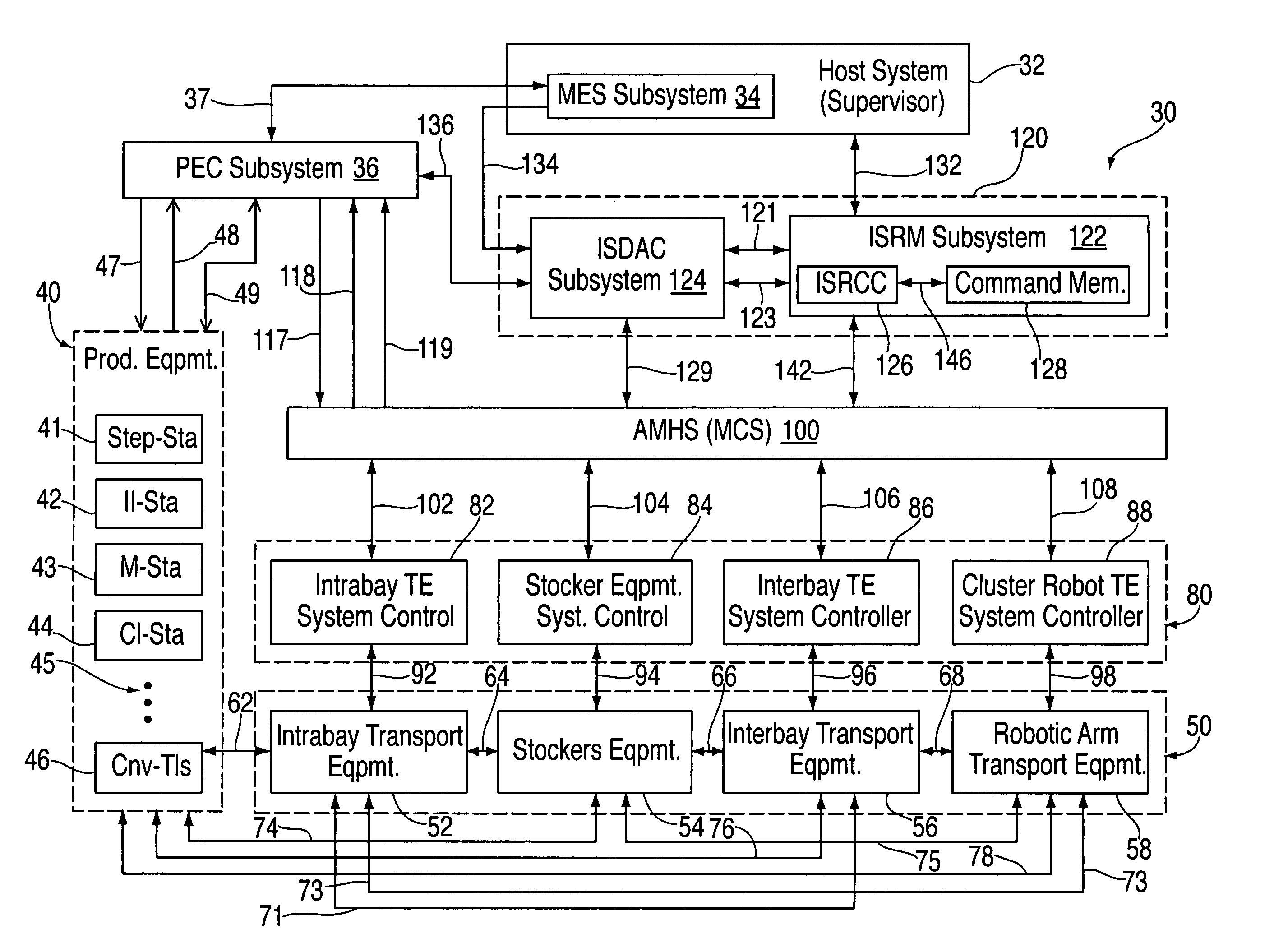
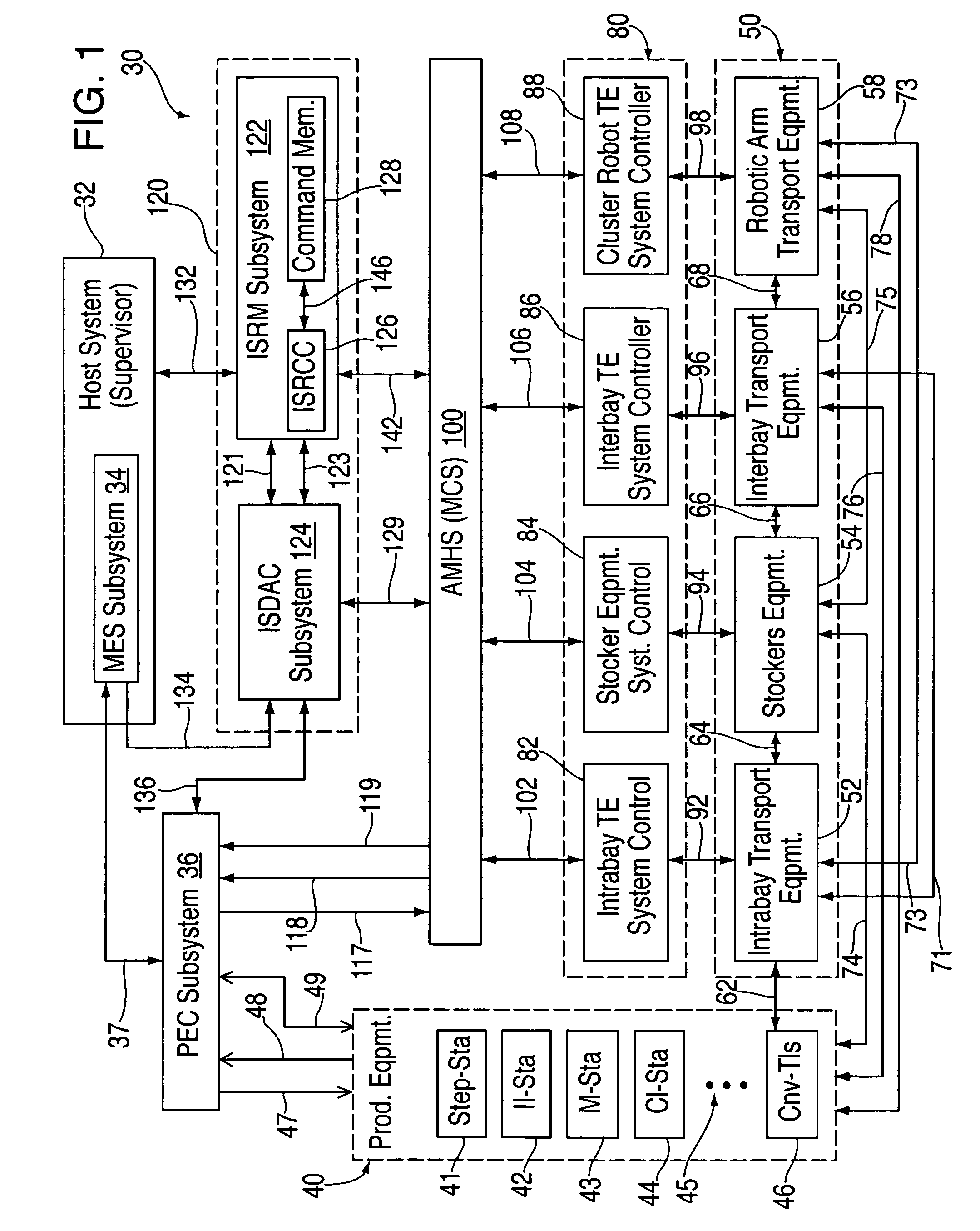
[0034]To better understand the systems and methods of the present invention, it is useful to consider, as shown in FIG. 1, a simplified block diagram showing an exemplary known factory automation (FA) system, sometimes called a Computer Integrated Manufacturing (CIM) system, in which the system of the present invention, shown in summary form in dashed blo...


PUM


Abstract

Automatic error recovery systems and methods for automated manufacturing plants and factories are disclosed. Such facilities normally have multiple automated control systems, including an automated material handling system (AMHS), all of which run automatically, typically under the control of a computerized manufacturing execution system (MES). The disclosed issue resolution (ISR) systems and methods involve providing components, which may be supervised and operated by an issue resolution management (ISRM) system, if desired, that interfaces with the MES, AMHS, and / or production control system(s) which operate the tools and other stations within the automated factory. The components, which may be considered customized logic cells, may each be written for handling a specific kind of incoming error condition, problem or other issue that might occur and which is amenable to automatic resolution or recovery. These errors often occur between or across the boundaries of the various interactive systems and automated equipment. Each cell may cycle through a sequence of possible error resolution or recovery steps until the specific issue is resolved or until the sequence of steps is exhausted. Other components of the ISR system may provide results-oriented messages and / or facilitate the collection of data as to whether and which corrective commands from the ISR system resolved the reported error conditions automatically. The disclosed ISR systems and methods for resolving errors and other issues automatically helps improve the overall productivity of automated factories by reducing downtime and the need for human intervention to correct problems, thereby increasing factory throughput.

Description

BACKGROUND OF THE INVENTION[0001]The present invention relates in general to fully automated systems and methods for operating industrial equipment, such as automated semiconductor fabrication facilities, and relates in particular to automated systems and methods for resolving error conditions and other issues which occur in manufacturing facilities which utilize automated manufacturing execution systems, material control systems and real-time dispatching systems.[0002]Computer Integrated Manufacturing (CIM) systems used in automated IC fabrication facilities (fabs), such as a facility for processing 200 mm or 300 mm wafers, may include the following:[0003](1) an automated manufacturing execution system (MES) such as IBM's SiView Standard MES (from IBM Japan Industrial Solution Co., Ltd, (iiSC));[0004](2) an automated material handling system (AMHS) such as the Muratec material control system (MCS) from Murata Machinery, Ltd. and / or an automated reticle handling system (ARHS); and[0...

Claims


Application Information

Patent Timeline
Patent Type & Authority Patents(United States)
IPC IPC(8): G06F17/00G06N5/02G05B9/02G05B13/00G05B19/418G05B23/00G06F19/00
CPCG05B19/4189G05B2219/45031G05B2219/32239G05B2219/31272Y02P90/02Y02P90/80G05B19/418
Inventor GARTLAND, KARLRAMPHAL, ZHENYA D.TOMITA, YUJITRAVAGLINE, DAVID L.
Owner INT BUSINESS MASCH CORP
Learn More