Optical mapping apparatus
a technology of optical mapping and optical tracing, which is applied in the field of optical tracing apparatus, can solve the problems of reducing the efficiency of correctors, reducing system complexity, and affecting the use of patients, and achieves the effect of efficient us
- Summary
- Abstract
- Description
- Claims
- Application Information
AI Technical Summary
Benefits of technology
Problems solved by technology
Method used
Image
Examples
first embodiment
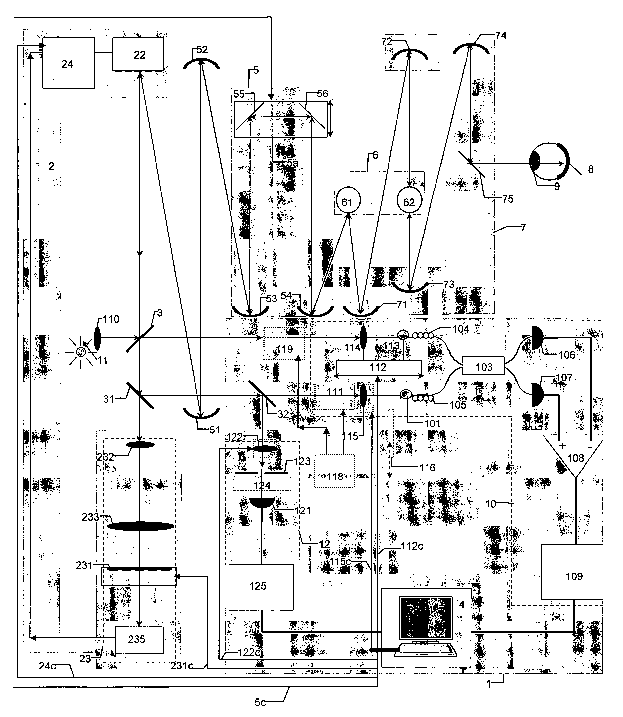
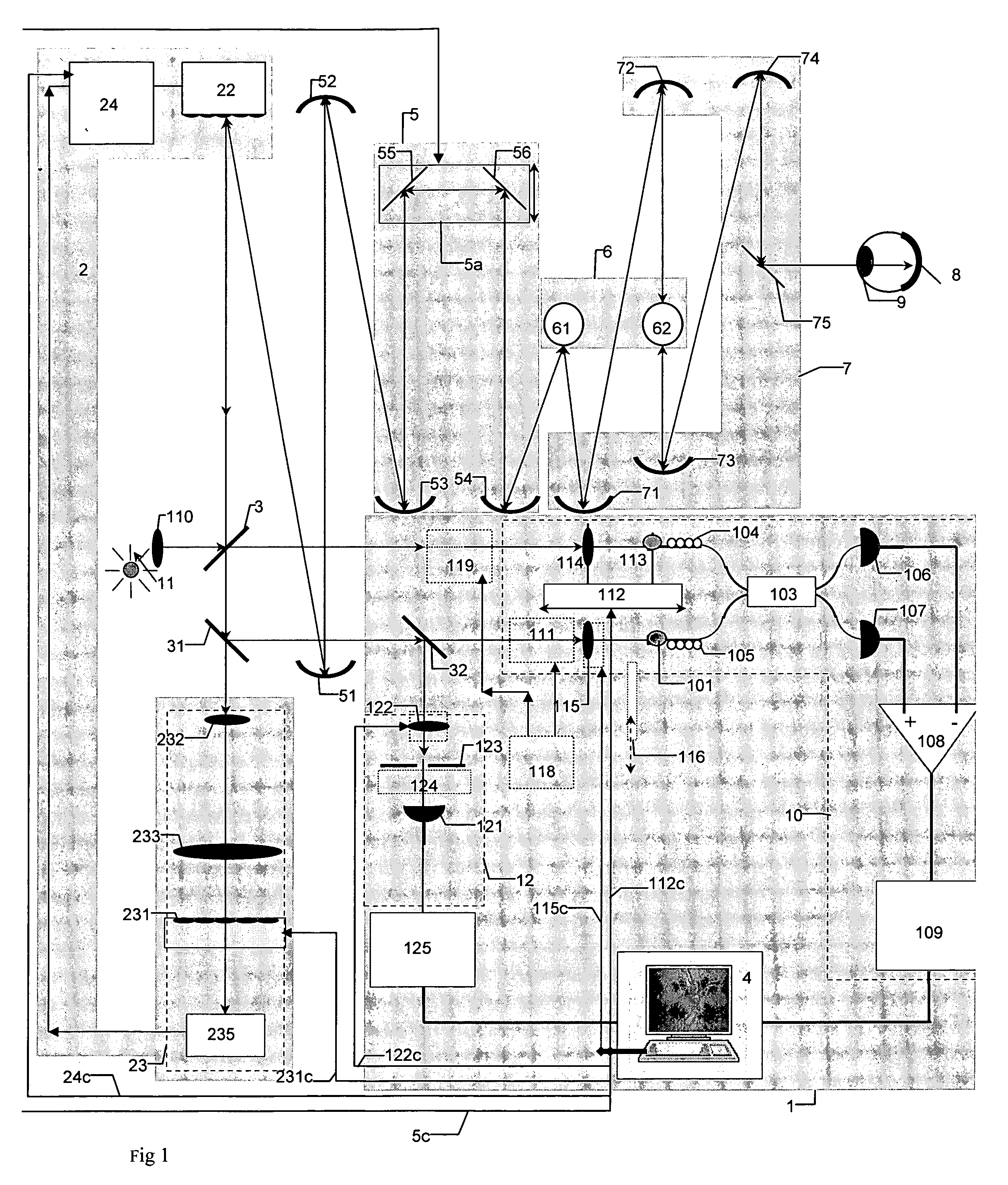
[0111]FIG. 1 shows the high resolution imaging system according to an embodiment of the invention. Light from a low coherence source 11 is collimated via focusing element 110 and divided by an OCT beamsplitter, 3 into two beams, a reference beam and an object beam. The object beam is sent towards a wavefront corrector 22, wherefrom the beam is transferred via the a telescope, equipped with curved mirrors 51, 52 towards focusing optics 5, constructed from curved mirrors 53, 54 and flat mirrors 55, 56 in a Badal configuration. The object beam is then sent to a transverse scanner 6, constructed from a line scanner 61 and a frame scanner 62. The scanner 6 is arranged to scan beams from the source 11 over a predetermined area. Interface optics 7, consisting of curved mirrors 71-74 and flat mirror 75 are provided to transfer a beam from the scanner 6 to the object to be imaged, 8. The curved mirrors 51-54 and 71-74 could be parabolic or spherical. In FIG. 1, the object 8 is the retina beh...
fifth embodiment
[0213]FIG. 6 shows the system for high resolution imaging, where a common focus element 110 is used for both OCT and confocal channels in the uncommon path. The OCT splitter 3 is in single mode fibre and tied by fibre to transfer light from the object 8 to the input 101 of the balanced splitter 103. The aperture of the confocal receiver at the core of the OCT is now at the fibre tip 106 of the fibre 126, behind the splitter 32. Light diverges out from the aperture fibre. 100. By axially moving the collimating element 110, the convergence of the beam sent to the interface optics 7 changes. The aperture of the OCT input, 100, is conjugate by virtue of beamsplitter 32 with the confocal aperture 106, here implemented in fibre 126, which could be single mode or multimode. Input 110 could be moved under computer, e,g, PC 4 control, showed by control line 110c. Irrespective of focus correction by elements 55 and 56, or the deformation of the corrector 22, the two fibre apertures 100 and 10...
PUM
 Abstract
Description
Claims
Application Information
 - R&D
- Intellectual Property
- Life Sciences
- Materials
- Tech Scout
- Unparalleled Data Quality
- Higher Quality Content
- 60% Fewer Hallucinations
Browse by: Latest US Patents, China's latest patents, Technical Efficacy Thesaurus, Application Domain, Technology Topic, Popular Technical Reports.
© 2025 PatSnap. All rights reserved.Legal|Privacy policy|Modern Slavery Act Transparency Statement|Sitemap|About US| Contact US: help@patsnap.com


