Oxynitride fluorescent material and light-emitting device
a technology of oxynitride and fluorescent material, which is applied in the direction of discharge tube/lamp details, natural mineral layered products, gas-filled discharge tubes, etc., can solve the problems of luminance drop, and achieve the effect of reducing luminance drop, reducing deterioration, and reducing luminance drop
- Summary
- Abstract
- Description
- Claims
- Application Information
AI Technical Summary
Benefits of technology
Problems solved by technology
Method used
Image

Examples
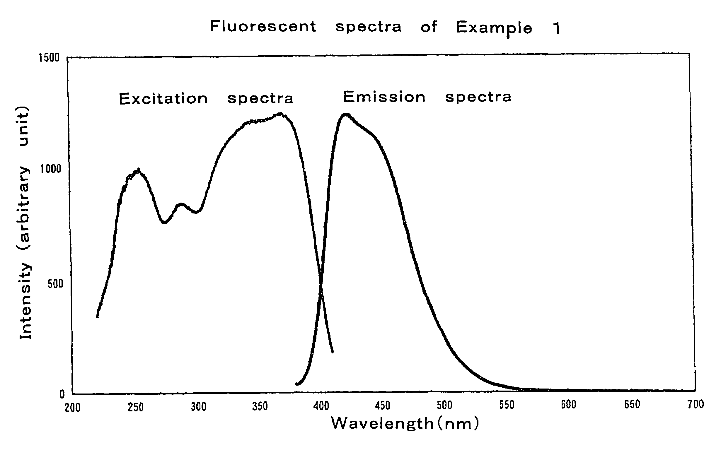
example 1
[0078]The starting powders used were silicon nitride powders having an average particle diameter of 0.5 μm, an oxygen content of 0.93% by weight and α-type content of 92%, lanthanum oxide powders with a 99.9% purity and cerium oxide powders with a 99.9% purity.
[0079]The silicon nitride, lanthanum oxide and cerium oxide powders were weighed in the respective amounts of 46.01% by weight, 43.27% by weight and 10.72% by weight so as to obtain a compound having a compositional formula Ce0.57La2.43Si9N12O4.5 (with mixture compositions of the starting powders shown in Table 1 and compositional parameters shown in Table 2). Then, the powders were mixed together with the addition of hexane in a ball mill for 2 hours, followed by drying in a rotary evaporator. The ensuring compound was molded in a mold with the application of a pressure of 20 MPa to obtain a compact of 12 mm in diameter and 5 mm in thickness.
[0080]That compact was placed in a boron nitride crucible, which was then set in an e...
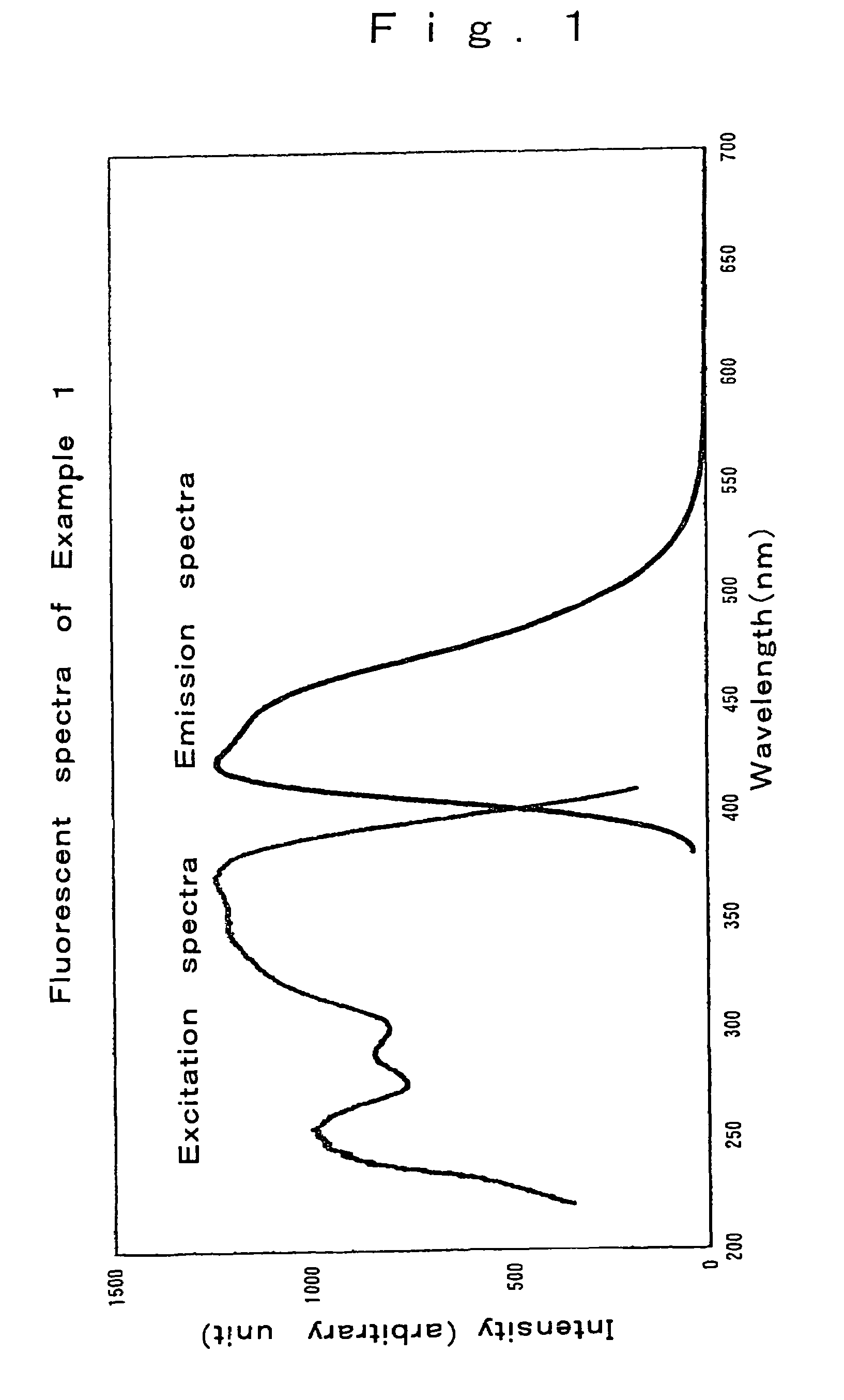
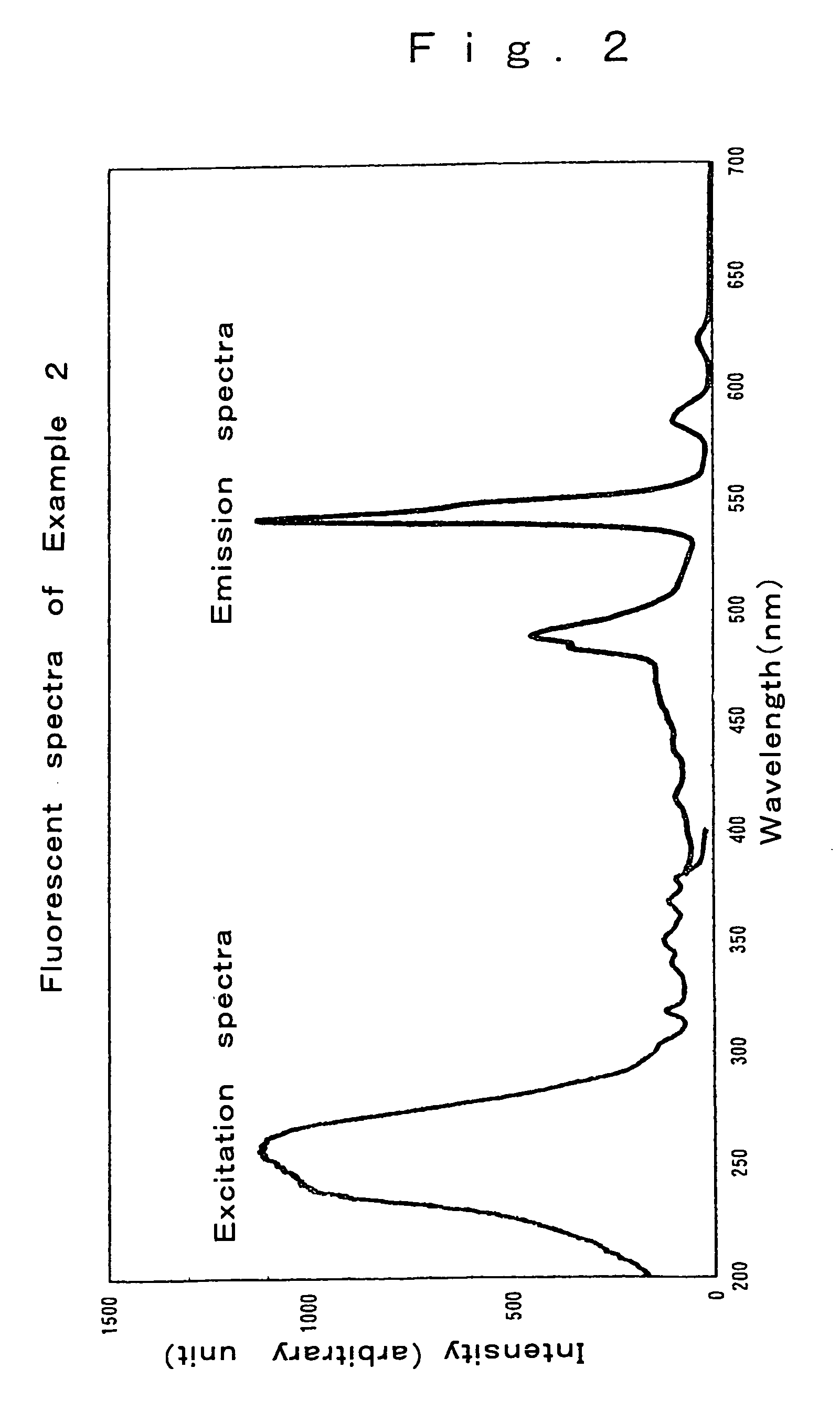
examples 2-10
[0083]The starting powders used herein were the same silicon nitride powders, lanthanum oxide powders and cerium nitride powders as in Example 1 as well as europium oxide powders with a 99.9% purity, terbium oxide powders with a 99.9% purity, aluminum oxide powders with a 99.9% purity and lanthanum oxide powders with a 99.9% purity. Oxynitride powders were prepared following Example 1 with the exception that the compositions set out in Tables 1 and 2 were used. As a consequence of X-ray diffractometry upon pulverization of the synthesized samples, the compositions in Examples 2 to 8 were all identified as the La3Si8N11O4 phase, and the compositions in Examples 9 and 10 were all identified as the La3Si8−xAlxN11−xO4+x phase. Further, there were obtained fluorescent materials that were excited by ultraviolet radiation to give out visible light with high luminance, as shown in Examples 2 to 10 in Table 3. In particular, the samples with Ce added thereto provided excellent blue fluoresce...
PUM
| Property | Measurement | Unit |
|---|---|---|
| wavelength | aaaaa | aaaaa |
| wavelength | aaaaa | aaaaa |
| wavelength | aaaaa | aaaaa |
Abstract
Description
Claims
Application Information
 - R&D
- Intellectual Property
- Life Sciences
- Materials
- Tech Scout
- Unparalleled Data Quality
- Higher Quality Content
- 60% Fewer Hallucinations
Browse by: Latest US Patents, China's latest patents, Technical Efficacy Thesaurus, Application Domain, Technology Topic, Popular Technical Reports.
© 2025 PatSnap. All rights reserved.Legal|Privacy policy|Modern Slavery Act Transparency Statement|Sitemap|About US| Contact US: help@patsnap.com